4.3.1 Main circuit connection diagram
4.3.1.1 For VFDs of AC 3PH 380 V (-15%)–440 V (+10%)
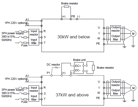
Figure 4‑7 Connection diagram of main circuit for the VFDs of 380 V
Note:
1. The fuse, DC reactor, brake unit, brake resistor, input reactor, input filter, output reactor, and output filter are optional parts. Please refer to Appendix D "Optional peripheral accessories" for detailed information.
2. A1 and A2 are optional parts.
3. P1 and (+) are short circuited in factory for the VFDs of 380 V (≥37 kW), if need to connect with the DC rector, please remove the contact tag between P1 and (+).
4. Before connecting the brake resistor cable, remove the yellow labels of PB, (+), and (-) from the terminal blocks. Otherwise, poor connection may occur.
4.3.1.2 For VFDs of AC 3PH 520 V (-15%)–690 V (+10%)
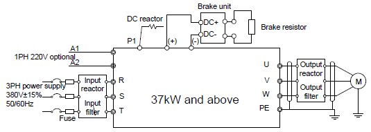
Figure 4‑8 Connection diagram of main circuit for the VFDs of 660 V
Note:
1. The fuse, DC reactor, brake unit, brake resistor, input reactor, input filter, output reactor, output filter are optional parts. Please refer to Appendix D "Optional peripheral accessories" for detailed information.
2. P1 and (+) are short circuited in factory, if need to connect with the DC rector, please remove the contact tag between P1 and (+).
3. When connecting the brake resistor, take off the yellow warning label marked with (+) and (-) on the terminal bar before connecting brake resistor wire, otherwise, poor contact will occur.
4.3.2 Terminals figure of main circuit
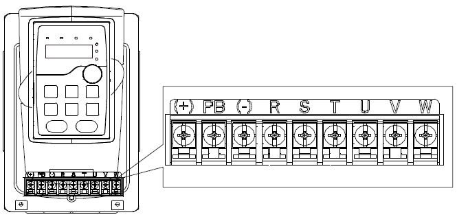
Figure 4‑9 Terminals of main circuit for the VFDs of 380 V 1.5–2.2 kW
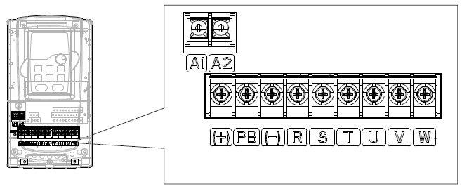
Figure 4‑10 Terminals of main circuit for the VFDs of 380 V 4–5.5 kW
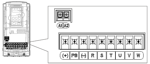
Figure 4‑11 Terminals of main circuit for the VFDs of 380 V 7.5–11 kW
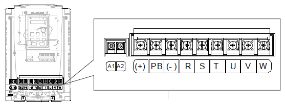
Figure 4‑12 Terminals of main circuit for the VFDs of 380 V 15–18 kW
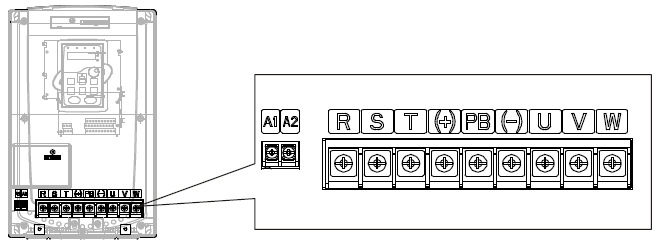
Figure 4‑13 Terminals of main circuit for the VFDs of 380 V 22–30 kW
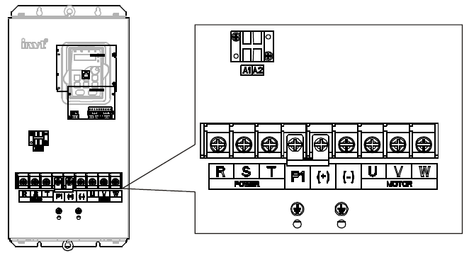
Figure 4‑14 Terminals of main circuit for the VFDs of 380 V 37–55 kW and 660 V 22–45 kW
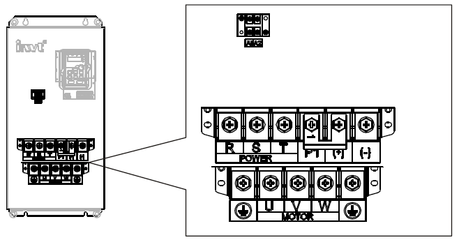
Figure 4‑15 Terminals of main circuit for the VFDs of 380 V 75–110 kW and 660 V 55–132 kW
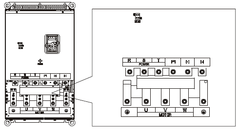
Figure 4‑16 Terminals of main circuit for the VFDs of 380 V 132–200 kW and 660 V 160–220 kW
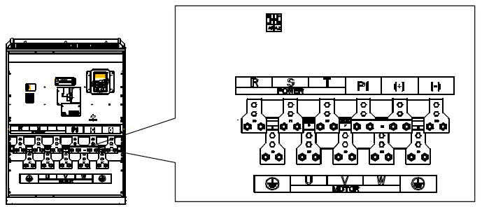
Figure 4‑17 Terminals of main circuit for the VFDs of 380 V 220–315 kW and 660 V 250–350 kW
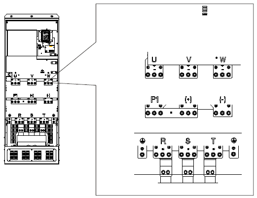
Figure 4‑18 Terminals of main circuit for the VFDs of 660 V 400–630 kW
Terminal | Terminal name | Function | |
380 V ≤30 kW | 380 V ≥37 kW | ||
660 V | |||
R, S, T | Power input of the main circuit | 3-phase AC input terminals which are generally connected with the power supply. | |
U, V, W | The VFD output | 3-phase AC output terminals which are generally connected with the motor. | |
P1 | / | DC reactor terminal 1 | P1 and (+) are connected with the terminals of DC reactor. (+) and (-) are connected with the terminals of brake unit. PB and (+) are connected with the terminals of brake resistor. |
(+) | Brake resistor 1 | DC reactor terminal 2, brake unit terminal 1 | |
(-) | / | Brake unit terminal 2 | |
PB | Brake resistor 2 | / | |
PE | 380 V: the grounding resistor is less than 10Ohm | Protective grounding terminals, every machine is provided 2 PE terminals as the standard configuration. These terminals should be grounded with proper techniques. | |
660 V: the grounding resistor is less than 10Ohm | |||
A1 and A2 | Control power supply terminal | Optional for the VFDs of 380 V, standard for the VFDs of 660 V (with external 220 V control power) If no voltage is present on the main circuit, more convenient and safer commissioning is available through the auxiliary power supply. | |
Note:
1. Do not use an asymmetrically constructed motor cable. If there is a symmetrically constructed grounding conductor in the motor cable in addition to the conductive shield, connect the grounding conductor to the grounding terminal at the VFD and motor ends.
2. Brake resistor, brake unit and DC reactor are optional parts.
3. Route the motor cable, input power cable and control cables separately.
4. If the terminal description is "/", the machine does not provide the terminal as the external terminal.
4.3.3 Wiring of terminals in main circuit
1. Connect the ground wire of the input power cable to the ground terminal (PE) of the VFD, and connect the 3PH input cable to the terminals R, S, and T, and fasten them up.
2. Connect the ground wire of the motor cable to the ground terminal of the VFD, and connect the 3PH motor cable to the terminals U, V, and W, and fasten them up.
3. Connect the brake resistor and other accessories that are equipped with cables to the specified positions.
4. Fasten all the cables outside of the VFD mechanically, if possible.