Function code | Name | Detailed instruction of parameters | Default value | Modify |
P00 Group Basic function group | ||||
P00.00 | Speed control mode | 0: Sensorless vector control mode 0 (apply to AM and SM) No need to install encoders. It is suitable in cases with low frequency, big torque and high speed control accuracy for accurate speed and torque control. Relative to mode 1, this mode is more suitable for medium and small power. 1: Sensorless vector control mode 1 (applying to AM) No need to install encoders. It is suitable in cases with high speed control accuracy for accurate speed and torque control at all power ratings. 2: SVPWM control No need to install encoders. It can improve the control accuracy with the advantages of stable operation, valid low-frequency torque boost and current vibration suppression and the functions of slip compensation and voltage adjustment. 3: Closed-loop vector control Need to install encoders. It is suitable in cases with low frequency, high speed control accuracy for accurate speed and torque control. Note: AM-Asynchronous Motor; SM-Synchronous Motor; motor parameter autotuning should be performed on the VFD before vector mode is adopted. | 2 | ◎ |
P00.01 | Run command channel | Select the run command channel of the VFD. The control command of the VFD includes: start-up, stop, forward, reverse, jogging and fault reset. 0: Keypad running command channel ("LOCAL/REMOT" light off) Carry out the command control by RUN, STOP/RST on the keypad. Set the multi-function key QUICK/JOG to FWD/REV shifting function (P07.02=3) to change the running direction; press RUN and STOP/RST simultaneously in running state to make the VFD coast to stop. 1: Terminal running command channel ("LOCAL/REMOT" flickering) Carry out the running command control by the forward rotation, reverse rotation and forward jogging and reverse jogging of the multi-function terminals 2: Communication running command channel ("LOCAL/REMOT" on); The running command is controlled by the upper monitor via communication | 0 | ○ |
P00.02 | Communi cation running commands | Select the controlling communication command channel of the VFD. 0: Modbus communication channel 1: PROFIBUS\CANopen communication channel 2: Ethernet communication channel 3: Reserved Note: 1, 2 and 3 are extension functions which need corresponding extension cards. | 0 | ○ |
P00.03 | Max. output frequency | This parameter is used to set the maximum output frequency of the VFD. Users should pay attention to this parameter because it is the foundation of the frequency setting and the speed of acceleration and deceleration. Setting range: P00.04–400.00 Hz | 50.00 Hz | ◎ |
P00.04 | Upper limit of the running frequency | The upper limit of the running frequency is the upper limit of the output frequency of the VFD which is lower than or equal to the maximum frequency. Setting range: P00.05–P00.03 (max. output frequency) | 50.00 Hz | ◎ |
P00.05 | Lower limit of the running frequency | The lower limit of the running frequency is that of the output frequency of the VFD. The VFD runs at the lower limit frequency if the set frequency is lower than the lower limit one. Note: Max. output frequency ≥ Upper limit frequency ≥ Lower limit frequency Setting range: 0.00 Hz–P00.04 (Upper limit of the running frequency) | 0.00 Hz | ◎ |
P00.06 | A frequency command | Note: Frequency A and frequency B cannot use the same frequency setting mode. The frequency source can be set by P00.09. 0: Keypad Modify the value P00.10 (set the frequency by keypad) to modify the frequency by the keypad. 1: AI1 2: AI2 3: AI3 Set the frequency by analog input terminals. Goodrive35 series VFDs provide 3 analog input terminals as the standard configuration, of which AI1/AI2 are the voltage/current option (0–10 V/0–20mA) which can be shifted by jumpers; while AI3 is voltage input (-10 V–+10 V). Note: When AI1/AI2 select 0–20mA input, the corresponding voltage of 20mA is 10 V. 100.0% of the analog input setting corresponds to the maximum frequency (function code P00.03) in forward direction and -100.0% corresponds to the maximum frequency in reverse direction (function code P00.03) 4: High-speed pulse HDI setting The frequency is set by high-speed pulse terminals. Goodrive35 series VFDs provide 1 high speed pulse input as the standard configuration. The pulse frequency range is 0.00–50.00 kHz. 100.0% of the high speed pulse input setting corresponds to the maximum frequency in forward direction (P00.03) and -100.0% corresponds to the maximum frequency in reverse direction (P00.03). Note: The pulse setting can only be input by multi-function terminals HDI. Set P05.00 (HDI input selection) to high speed pulse input, and set P05.49 (HDI high speed pulse input function selection) to frequency setting input. 5: Simple PLC program setting The VFD runs at simple PLC program mode when P00.06=5 or P00.07=5. Set P10 (simple PLC and multi-step speed control) to select the running frequency, running direction, ACC/DEC time and the keeping time of corresponding stage. See the function description of P10 for detailed information. 6: Multi-step speed running setting The VFD runs at multi-step speed mode when P00.06=6 or P00.07=6. Set P05 to select the current running stage, and set P10 to select the current running frequency. The multi-step speed has the priority when P00.06 or P00.07 does not equal to 6, but the setting stage can only be the 1–15 stage. The setting stage is 0–15 if P00.06 or P00.07 equals to 6. 7: PID control setting The running mode of the VFD is process PID control when P00.06=7 or P00.07=7. It is necessary to set P09. The running frequency of the VFD is the value after PID effect. See P09 for the detailed information of the given source, given value, feedback source of PID. 8: Modbus communication setting The frequency is set by Modbus communication. See P14 for detailed information. 9: PROFIBUS/CANopen communication setting The frequency is set by PROFIBUS/ CANopen communication. See P15 for the detailed information. 10: Ethernet communication setting (reserved) See P16 for the detailed information. 11: Reserved 12: Pulse string AB setting | 0 | ○ |
P00.07 | B frequency command | 2 | ○ | |
P00.08 | B frequency command reference | 0: Maximum output frequency, 100% of B frequency setting corresponds to the maximum output frequency 1: A frequency command, 100% of B frequency setting corresponds to the maximum output frequency. Select this setting if it needs to adjust on the base of A frequency command | 0 | ○ |
P00.09 | Combination of setting source | 0: A, the current frequency setting is A frequency command 1: B, the current frequency setting is B frequency command 2: A+B, the current frequency setting is A frequency command + B frequency command 3: A-B, the current frequency setting is A frequency command - B frequency command 4: Max (A, B): The bigger one between A frequency command and B frequency is the set frequency. 5: Min (A, B): The lower one between A frequency command and B frequency is the set frequency. Note: The combination manner can be shifted by P05 (terminal function) | 0 | ○ |
P00.10 | Keypad set frequency | When A and B frequency commands are selected as "keypad setting", the value of the function code is the original setting one of the frequency data of the VFD. Setting range: 0.00 Hz–P00.03 (max. output frequency) | 50.00 Hz | ○ |
P00.11 | ACC time 1 | ACC time means the time needed if the VFD speeds up from 0 Hz to max. output frequency (P00.03). DEC time means the time needed if the VFD speeds down from max. output frequency to 0 Hz (P00.03). Goodrive35 series VFDs define four groups of ACC/DEC time which can be selected by P05. The factory default ACC/DEC time of the VFD is the first group. Setting range of P00.11 and P00.12: 0.0–3600.0s | Depend on model | ○ |
P00.12 | DEC time 1 | Depend on model | ○ | |
P00.13 | Running direction | 0: Runs at the default direction, the VFD runs in the forward direction. FWD/REV indicator is off. 1: Runs at the reverse direction, the VFD runs in the reverse direction. FWD/REV indicator is on. Modify the function code to shift the rotation direction of the motor. This effect equals to the shifting the rotation direction by adjusting either two of the motor lines (U, V and W). The motor rotation direction can be changed by QUICK/JOG on the keypad. Refer to parameter P07.02. Note: When the function parameter comes back to the default value, the motor’s running direction will come back to the factory default state, too. In some cases it should be used with caution after commissioning if the change of rotation direction is disabled. 2: Forbid to run in reverse direction: It can be used in some special cases if reverse running is disabled. | 0 | ○ |
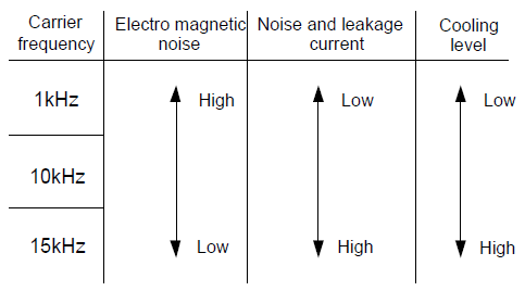
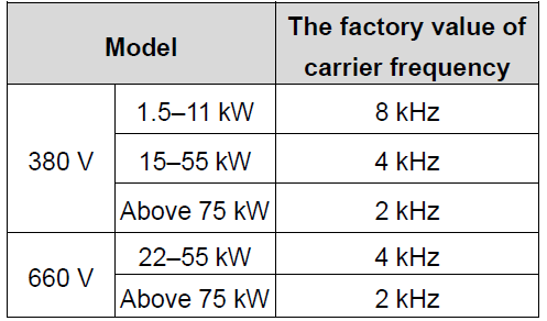
P00.14 | Carrier frequency setting |
The relationship table of the motor type and carrier frequency:
The advantage of high carrier frequency: ideal current waveform, little current harmonic wave and motor noise. The disadvantage of high carrier frequency: increasing the switch loss, increasing VFD temperature and the impact to the output capacity. The VFD needs to derate on high carrier frequency. At the same time, the leakage and electrical magnetic interference will increase. Applying low carrier frequency is contrary to the above, too low carrier frequency will cause unstable running, torque decreasing and surge. The manufacturer has set a reasonable carrier frequency when the VFD is in factory. In general, users do not need to change the parameter. When the frequency used exceeds the default carrier frequency, the VFD needs to derate 10% for each additional 1k carrier frequency. Setting range: 1.2–15.0 kHz | Depend on model | ○ |
P00.15 | Motor parameter autotuning | 0: No operation 1: Rotation autotuning Comprehensive motor parameter autotune It is recommended to use rotation autotuning when high control accuracy is needed. 2: Static autotuning 1 (autotune totally); It is suitable in the cases when the motor cannot de-couple from the load. The autotuning for the motor parameter will impact the control accuracy. 3: Static autotuning 2 (autotune part parameters); when the current motor is motor 1, autotune P02.06, P02.07, P02.08; and when the current motor is motor 2, autotune P12.06, P12.07, P12.08. | 0 | ◎ |
P00.16 | AVR function selection | 0: Invalid 1: Valid during the whole procedure The auto-adjusting function of the VFD can cancel the impact on the output voltage of the VFD because of the bus voltage fluctuation. | 1 | ○ |
P00.17 | Reserved | Reserved | 0 | ◎ |
P00.18 | Function restore parameter | 0: No operation 1: Restore the default value 2: Cancel the fault record Note: The function code will restore to 0 after finishing the operation of the selected function code. Restoring to the default value will cancel the user password, please use this function with caution. | 0 | ◎ |