Function code | Name | Detailed instruction of parameters | Default value | Modify |
P01.00 | Start mode | 0: Start-up directly: start from the starting frequency P01.01 1: Start-up after DC brake: start the motor from the starting frequency after DC brake (set the parameter P01.03 and P01.04). It is suitable in the cases where reverse rotation may occur to the low inertia load during starting. 2: Start-up after speed tracing: start the rotating motor smoothly after tracking the rotation speed and direction automatically. It is suitable in the cases where reverse rotation may occur to the big inertia load during starting. Note: The VFDs above 4 kW have the function. | 0 | ◎ |
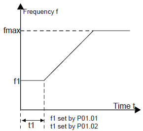
P01.01 | Starting frequency of direct start | Starting frequency of direct start-up means the original frequency during the VFD starting. See P01.02 for detailed information. Setting range: 0.00–50.00 Hz | 0.00 Hz | ◎ |
P01.02 | Retention time of starting frequency |
Set a proper starting frequency to increase the torque of the VFD during starting. During the retention time of the starting frequency, the output frequency of the VFD is the starting frequency. And then, the VFD will run from the starting frequency to the set frequency. If the set frequency is lower than the starting frequency, the VFD will stop running and keep in the stand-by state. The starting frequency is not limited in the lower limit frequency. Setting range: 0.0–50.0s | 0.0 s | ◎ |
P01.03 | The brake current before starting | The VFD will carry out DC brake at the brake current set before starting and it will speed up after the DC brake time. If the DC brake time is set to 0, the DC brake is invalid. The stronger the brake current, the bigger the brake power. The DC brake current before starting means the percentage of the rated current of the VFD. The setting range of P01.03: 0.0–100.0% The setting range of P01.04: 0.0–30.0s | 0.0% | ◎ |
P01.04 | The brake time before starting | 0.0 s | ◎ | |
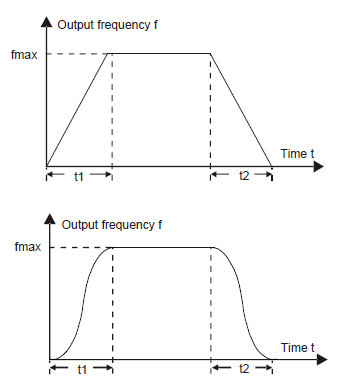
P01.05 | ACC/DEC selection | The changing mode of the frequency during start-up and running. 0: Linear type. The output frequency increases or decreases linearly. 1: S curve. The output frequency increases or decreases according to the S curve. S curve is generally used in cases where smooth startup/stop is required eg elevator, conveyor belt, etc.
| 0 | ◎ |
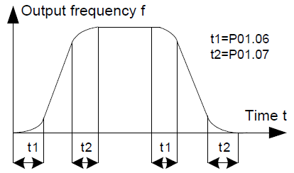
P01.06 | ACC time of the starting step of S curve | The curve rate of S curve is determined by the acceleration range and acceleration/deceleration time.
Setting range: 0.0–50.0s | 0.1 s | ◎ |
P01.07 | DEC time of the ending step of S curve | 0.1 s | ◎ | |
P01.08 | Stop mode | 0: Decelerate to stop: after the stop command becomes valid, the VFD decelerates to decrease the output frequency during the set time. When the frequency decreases to P01.15, the VFD stops. 1: Coast to stop: after the stop command becomes valid, the VFD ceases the output immediately. And the load coasts to stop at the mechanical inertia. | 0 | ○ |
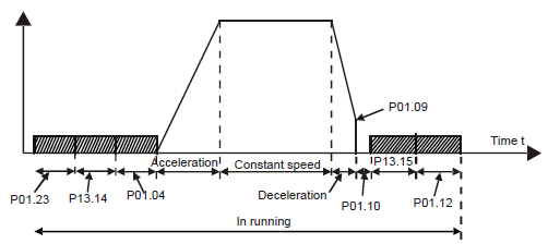
P01.09 | Starting frequency of DC brake | The starting frequency of stop brake: The VFD will carry on stop DC brake when the frequency is arrived during the procedure of decelerating to stop. Demagnetizing time: Before the stop DC brake, the VFD will close output and begin to carry on the DC brake after the waiting time. This function is used to avoid the overcurrent fault caused by DC brake when the speed is too high. Stop DC brake current: the DC brake added. The stronger the current, the bigger the DC brake effect. The brake time of stop brake: the retention time of DC brake. If the time is 0, the DC brake is invalid. The VFD will stop at the set deceleration time.
Setting range of P01.09: 0.00 Hz–P00.03 (max. output frequency) Setting range of P01.10: 0.00–30.00s Setting range of P01.11: 0.0–100.0% Setting range of P01.12: 0.0–50.0s | 0.00 Hz | ○ |
P01.10 | Demagne tizing time | 0.00 s | ○ | |
P01.11 | DC brake current | 0.0% | ○ | |
P01.12 | DC brake time | 0.0 s | ○ | |
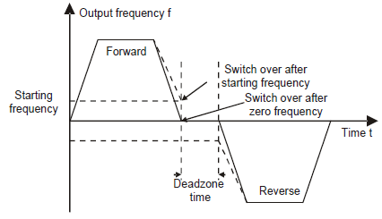
P01.13 | Dead time of FWD /REV rotation | During the procedure of switching for/rev rotation, set the threshold by P01.14, which is as the table below:
Setting range: 0.0–3600.0s | 0.0 s | ○ |
P01.14 | Shifting between FWD /REV rotation | Set the threshold point of the VFD: 0: Switch after zero frequency 1: Switch after the starting frequency | 0 | ◎ |
P01.15 | Stopping speed | 0.00–100.00 Hz | 0.20 Hz | ◎ |
P01.16 | Detection of stopping speed | 0: Detect according to speed setting (no stopping delay) 1: Detect according to speed feedback (only valid for vector control) | 0 | ◎ |
P01.17 | Detection time of the feedback speed | If set P01.16 to 1, the feedback frequency is less than or equal to P01.15 and detect in the set time of P01.17, the VFD will stop; otherwise the VFD will stop after the set time of P01.17.
Setting range: 0.0–100.0s (only valid when P01.16=1) | 0.5 s | ◎ |
P01.18 | Terminal running protection when powering on | When the running commands are controlled by the terminal, the system will detect the state of the running terminal during powering on. 0: The terminal running command is invalid when powering on. Even the running command is detected to be valid during powering on, the VFD won’t run and the system keeps in the protection state until the running command is canceled and enabled again. 1: The terminal running command is valid when powering on. If the running command is detected to be valid during powering on, the system will start the VFD automatically after the initialization. Note: this function should be selected with cautions, or serious result may follow. | 0 | ○ |
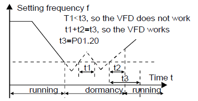
P01.19 | Action if running frequency< lower limit frequency (valid >0) | This function code determines the running state of the VFD when the set frequency is lower than the lower-limit one. 0: Run at the lower-limit frequency 1: Stop 2: Hibernation 3: Run at zero frequency The VFD will coast to stop when the set frequency is lower than the lower-limit one. If the set frequency is above the lower limit one again and it lasts for the time set by P01.20, the VFD will come back to the running state automatically. | 0 | ◎ |
P01.20 | Hibernation restore delay time | This function code determines the hibernation delay time. When the running frequency of the VFD is lower than the lower limit one, the VFD will pause to stand by. When the set frequency is above the lower limit one again and it lasts for the time set by P01.20, the VFD will run automatically.
Setting range: 0.0–3600.0s (valid when P01.19=2) | 0.0 s | ○ |
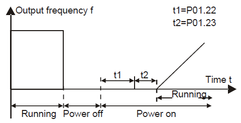
P01.21 | Restart after power off | This function can enable the VFD start or not after the power off and then power on. 0: Disable 1: Enable, if the starting need is met, the VFD will run automatically after waiting for the time defined by P01.22. | 0 | ○ |
P01.22 | The waiting time of restart after power off | The function determines the waiting time before the automatic running of the VFD when powering off and then powering on.
Setting range: 0.0–3600.0 s (valid when P01.21=1) | 1.0 s | ○ |
P01.23 | Start delay time | The function determines the brake release after the running command is given, and the VFD is in a stand-by state and wait for the delay time set by P01.23 Setting range: 0.00–60.00 s | 0.00 s | ○ |
P01.24 | Delay time of the stop speed | Setting range: 0.0–60.0 s | 0.0 s | ○ |
P01.25 | DEC time of E-stop | DEC time of E-stop (terminal function is set to 56). Setting range: 0.00–60.00 s | 2.00 s | ○ |