Function code | Name | Detailed instruction of parameters | Default value | Modify | |
P02.00 | Motor type 1 | 0: AM 1: SM Note: Switch the current motor by the switching channel of P08.31. | 0 | ◎ | |
P02.01 | Rated power of AM 1 | 0.1–3000.0 kW | Set the parameters of the controlled AM. In order to ensure control performance, set the value of P02.01–P02.05 based on the nameplate parameters. Goodrive35 series VFD provides parameter autotuning function. The accurate parameter autotuning requires proper parameter setup. In order to ensure control performance, configure the motor based on the motor which matches with the VFD. If the gap between motor power and the matched motor is too large, the control performance of the VFD will be deteriorated greatly. Note: P02.02–P02.10 can be initialized by resetting rated motor power P02.01. | Depend on model | ◎ |
P02.02 | Rated frequency of AM 1 | 0.01 Hz–P00.03 (max. output frequency) | 50.00 Hz | ◎ | |
P02.03 | Rated speed of AM 1 | 1–36000rpm | Depend on model | ◎ | |
P02.04 | Rated voltage of AM 1 | 0–1200 V | Depend on model | ◎ | |
P02.05 | Rated current of AM 1 | 0.8–6000.0A | Depend on model | ◎ | |
P02.06 | Stator resistor of AM 1 | 0.001–65.535Ω | After motor parameter autotuning finishes, the setting value of P02.06–P02.10 will be updated automatically. These parameters are the basic parameters for high-performance vector control, which will impact the control performance directly. Note: Users cannot change this group of parameters at will. | Depend on model | ○ |
P02.07 | Rotor resistor of AM 1 | 0.001–65.535Ω | Depend on model | ○ | |
P02.08 | Leakage inductance of AM 1 | 0.1–6553.5mH | Depend on model | ○ | |
P02.09 | Mutual inductance of AM 1 | 0.1–6553.5mH | Depend on model | ○ | |
P02.10 | Non-load current of AM 1 | 0.1–6553.5A | Depend on model | ○ | |
P02.11 | Magnetic saturation coefficient 1 for iron core of AM1 | 0.0–100.0% | 80.0% | ◎ | |
P02.12 | Magnetic saturation coefficient 2 for iron core of AM1 | 0.0–100.0% | 68.0% | ◎ | |
P02.13 | Magnetic saturation coefficient 3 for iron core of AM1 | 0.0–100.0% | 55.0% | ◎ | |
P02.14 | Magnetic saturation coefficient 4 for iron core of AM1 | 0.0–100.0% | 40.0% | ◎ | |
P02.15 | Rated power of SM 1 | 0.1–3000.0 kW | Set the parameters of controlled SM. In order to ensure control performance, set the value of P02.15–P02.19 based on the nameplate parameters of the motor. Goodrive35 series VFD provides parameter autotuning function. The accurate parameter autotuning requires proper parameter setup. In order to ensure control performance, configure the motor based on the motor which matches with the VFD. If the gap between motor power and the matching motor is too large, the control performance of the VFD will be deteriorated greatly. Note: P02.16–P02.19 can be initialized by resetting rated motor power P02.15. | Depend on model | ◎ |
P02.16 | Rated frequency of SM 1 | 0.01 Hz–P00.03 (max. output frequency) | 50.00 Hz | ◎ | |
P02.17 | Number of poles pairs for SM 1 | 1–128 | 2 | ◎ | |
P02.18 | Rated voltage of SM 1 | 0–1200 V | Depend on model | ◎ | |
P02.19 | Rated current of SM 1 | 0.8–6000.0 A | Depend on model | ◎ | |
P02.20 | Stator resistor of SM 1 | 0.001–65.535 Ω | After motor parameter autotuning finishes, the set value of P02.20–P02.22 will be updated automatically. These parameters are the basic parameters for high performance vector control, which will impact the control performance directly. When P00.15=1 (rotary autotuning), the set value of P02.23 can be updated automatically via autotuning; when P00.15=2 (static autotuning), the set value of P02.23 cannot be updated via autotuning, calculate the value of P02.23 and update it manually. | Depend on model | ○ |
P02.21 | Direct axis inductance of SM 1 | 0.01–6553.5 mH | Depend on model | ○ | |
P02.22 | Quadrature axis inductance of SM 1 | 0.01–655.35 mH | Depend on model | ○ | |
P02.23 | Back EMF constant of SM 1 | When P00.15=2, the set value of P02.23 cannot be updated by autotuning, please count according to the following method. The counter- electromotive force constant can be counted according to the parameters on the name plate of the motor. There are three ways to count: 1. If the name plate designate the counter-electromotive force constant Ke, then: E= (Ke*nN*2π)/ 60 2. If the name plate designate the counter-electromotive force constant E’ (V/1000r/min), then: E=E’*nN/1000 3. If the name plate does not designate the above parameters, then: E=P/√3*I In the above formulas: nN is the rated rotation speed, P is the rated power and I is the rated current. Setting range: 0–10000 | 320 | ○ | |
P02.24 | Reserved | ||||
P02.25 | Reserved | ||||
P02.26 | Motor 1 overload protection | 0: No protection 1: Common motor (with low speed compensation). Because the heat-releasing effect of the common motors will be weakened, the corresponding electric heat protection will be adjusted properly. The low speed compensation characteristic mentioned here means reducing the threshold of the overload protection of the motor whose running frequency is below 30 Hz. 2: Variable frequency motor (without low speed compensation) Because the heat-releasing effect of the specific motors won’t be impacted by the rotation speed, it is not necessary to adjust the protection value during low-speed running. | 2 | ◎ | |
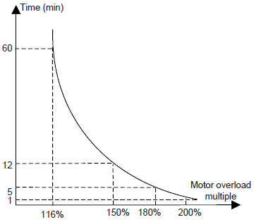
P02.27 | Motor 1 overload protection coefficient | Motor overload multiple M = Iout/(In × K) In is the rated current of the motor, Iout is the output current of the VFD and K is the motor overload protection coefficient. The smaller K is, the greater M is, and the more likely protection is implemented. When M=116%, protection is performed after motor overload lasts for 1 hour; when M=150%, protection is performed after motor overload lasts for 12 minutes; when M=180%, protection is performed after motor overload lasts for 5 minutes; when M=200%, protection is performed after motor overload lasts for 60 seconds; and when M≥ 400%, protection is performed immediately.
Setting range: 20.0%–120.0% | 100.0% | ○ | |
P02.28 | Motor 1 power display correction coefficient | This function code is used to adjust the power display value of motor 1 only. Setting range: 0.00–3.00 | 1.00 | ○ | |
P02.29 | Parameter display of motor 1 | 0: Display according to the motor type 1: Display all | 0 | ○ | |