Function code | Name | Detailed instruction of parameters | Default value | Modify |
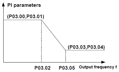
P03.00 | ASR proportional gain 1 | The parameters of P03.00–P03.05 are applicable only to the vector control mode. When the frequency is lower than P03.02 (Low-point frequency for switching), the ASR PI parameters are P03.00 and P03.01. When the frequency is higher than P03.05 (High-point frequency for switching), the ASR PI parameters are P03.03 and P03.04. When the frequency is between P03.02 and P03.05, the PI parameters are obtained based on the linear change of these two groups of parameters, as shown in the following figure.
You can adjust the dynamic response characteristics of the automatic speed regulator (ASR) in vector control by setting the ASR proportional gain and integral time. Both increasing the proportional gain and decreasing the integral time can accelerate the dynamic response of the ASR. However, if the proportional gain is too large or the integral time is too short, system oscillation or overadjustment may be caused. If the proportional gain is too small, system steady-state oscillation may be easily caused, and static speed error may also occur. The ASR PI parameters are closely related to the inertia of the system. The default PI parameters need to be modified based on the characteristics of loads to meet requirements of various scenarios. The setting range of P03.00: 0.0–200.0 The setting range of P03.01: 0.000–10.000s The setting range of P03.02: 0.00 Hz–P03.05 The setting range of P03.03: 0.0–200.0 The setting range of P03.04: 0.000–10.000s The setting range of P03.05: P03.02–P00.03 (max. output frequency) | 20.0 | ○ |
P03.01 | ASR integral time 1 | 0.200 s | ○ | |
P03.02 | Low-point frequency for switching | 5.00 Hz | ○ | |
P03.03 | ASR proportional gain 2 | 20.0 | ○ | |
P03.04 | ASR integral time 2 | 0.200 s | ○ | |
P03.05 | High-point frequency for switching | 10.00 Hz | ○ | |
P03.06 | ASR output filter | 0–8 (corresponds to 0–28/10 ms) | 0 | ○ |
P03.07 | Compen sation coefficient of electromotion slip | Slip compensation coefficient is used to adjust the slip frequency of the vector control and improve the speed control accuracy of the system. Adjusting the parameter properly can control the speed steady-state error. Setting range: 50%–200% | 100% | ○ |
P03.08 | Compen sation coefficient of brake slip | 100% | ○ | |
P03.09 | ACR proportional coefficient P | Note: 1. These two parameters adjust the PI adjustment parameter of the automatic current regulator (ACR). They directly affect the dynamic responding speed and control accuracy of the system. In general, you do not need to modify their default values. 2. Applied to SVC 0 (P00.00=0) and closed-loop vector control mode only (P00.00=3) 3. The value of this function code will be updated automatically after parameter autotuning of synchronous motor. Setting range: 0–20000 | 1000 | ○ |
P03.10 | ACR integral coefficient I | 1000 | ○ | |
P03.11 | Torque setting method | This parameter is used to enable the torque control mode, and set the torque. 0: Torque control is invalid 1: Keypad setting torque (P03.12) 2: Analog AI1 setting torque 3: Analog AI2 setting torque 4: Analog AI3 setting torque 5: Pulse frequency HDI setting torque 6: Multi-step torque setting 7: Modbus communication setting torque 8: PROFIBUS\CANopen communication setting torque 9: Ethernet communication setting torque 10: Reserved Note: Setting modes 2–10, 100% corresponds to three times of the rated current of the motor. | 0 | ○ |
P03.12 | Keypad setting torque | Setting range: -300.0%–300.0% (rated current of the motor) | 10.0% | ○ |
P03.13 | Torque reference filter time | 0.000–10.000s | 0.100 s | ○ |
P03.14 | Upper frequency of forward rotation in vector control | 0: Keypad (P03.16 sets P03.14, P03.17 sets P03.15) 1: AI1 2: AI2 3: AI3 4: Pulse frequency HDI setting upper-limit frequency 5: Multi-step setting upper-limit frequency 6: Modbus communication setting upper-limit frequency 7: PROFIBUS/CANopen communication setting upper-limit frequency 8: Ethernet communication setting upper-limit frequency Note: Setting method 0–8, 100% corresponds to the maximum frequency | 0 | ○ |
P03.15 | Upper frequency of reverse rotation in vector control | 0 | ○ | |
P03.16 | Keypad setting for upper frequency of forward rotation | This function is used to set the upper limit of the frequency. P03.16 determines the setting when P03.14=1; P03.17 determines the setting when P03.15=1. Setting range: 0.00 Hz–P00.03 (max. output frequency) | 50.00 Hz | ○ |
P03.17 | Keypad setting for upper frequency of reverse rotation | 50.00 Hz | ○ | |
P03.18 | Upper electromo tion torque source | This function code is used to select the electromotion and brake torque upper-limit setting source selection. 0: Keypad setting upper-limit frequency (P03.20 sets P03.18, P03.21 sets P03.19) 1: AI1 2: AI2 3: AI3 4: HDI 5: Modbus communication 6: PROFIBUS/CANopen communication 7: Ethernet communication Note: setting mode 1–7,100% corresponds to three times of the motor current. | 0 | ○ |
P03.19 | Upper brake torque source | 0 | ○ | |
P03.20 | Keypad setting of electromo tion torque | The function code is used to set the limit of the torque. Setting range: 0.0–300.0% (motor rated current) | 180.0% | ○ |
P03.21 | Keypad setting of brake torque | 180.0% | ○ | |
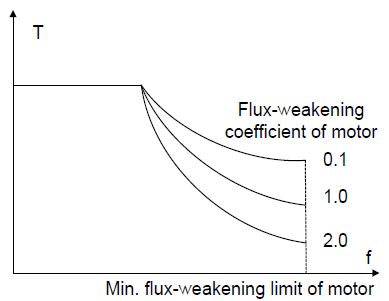
P03.22 | Weakening coefficient in constant power zone | The usage of AM in weakening control.
Function code P03.22 and P03.23 are effective at constant power. The motor will enter into the weakening state when the motor runs at rated speed. Change the weakening curve by modifying the weakening control coefficient. The bigger the weakening control coefficient is, the steeper the weak curve is. The setting range of P03.22: 0.10–2.00 The setting range of P03.23: 5%–50% | 1.00 | ○ |
P03.23 | Lowest weakening point in constant power zone | 20% | ○ | |
P03.24 | Max voltage limit | P03.24 set the max voltage of the VFD, which is dependent on the site situation. The setting range: 0.0–120.0% | 100.0% | ◎ |
P03.25 | Pre-exciting time | Preactivate the motor when the VFD starts up. Build up a magnetic field inside the VFD to improve the torque performance during the starting process. The setting time: 0.000–10.000s | 0.000 s | ○ |
P03.26 | Weak proportional gain | The response characteristic of the flux weakening controller is relative to P03.26 and P03.27. It can be adjusted properly. Setting range: 0–8000 | 1200 | ○ |
P03.27 | Integral gain of the flux weakening | 1200 | ○ | |
P03.28 | Control mode of flux weakening | 0x000–0x112 Ones: Control mode selection 0: Mode 0; 1: Mode 1; 2: Mode 2 Tens: Inductance compensation selection 0: Compensate 1: Not compensate Hundreds: High-speed control mode 0: Mode 0 1: Mode 1 | 0x000 | ○ |
P03.29 | Torque control mode | 0x0000–0x7111 Ones: Torque command selection 0: Torque reference 1: Torque current reference Tens: Torque compensation direction at 0 speed 0: Positive 1: Negative Hundreds: ASR integral separation setting 0: Disabled 1: Enabled Thousands: Torque control word setting Bit0: Torque command filtering mode 0: Inertia filter 1: Linear ACC/DEC filtering Bit1–2: ACC/DEC time for rotating speed upper limit 0: No ACC/DEC time 1: ACC/DEC time 1 2: ACC/DEC time 2 3: ACC/DEC time 3 | 0x0001 | ○ |
P03.30 | Low-speed friction torque | P03.30 is the compensation value of low-speed (<1.0 Hz) friction torque. P03.31 is the compensation value of high-speed (>P03.32) friction torque. The friction torque between low and high speed is the liner scale of P03.30 and P03.31. Note: Torque compensation is valid only in the torque control mode (P03.11≠0). Setting range of P03.30: 0.0–50.0% (rated torque of the motor) Setting range of P03.31: 0.0–50.0% (rated torque of the motor) Setting range of P03.32: 1.00 Hz–400.00 Hz | 0.0% | ○ |
P03.31 | High-speed friction torque | 0.0% | ○ | |
P03.32 | Correspond ing frequency of high- speed friction torque | 50.00 Hz | ○ |