Goodrive35 series VFDs provide internal SVPWM control which can be used in the cases where it does not need high control accuracy. It is also recommended to use SVPWM control when one VFD drives multiple motors.
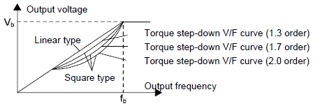
Goodrive35 series VFDs provide multiple V/F curve modes. The user can select the corresponding V/F curve to the site needs. Or they can set the corresponding V/F curve to their own needs.
Suggestions:
1. For the load of constant torque, such as the conveyor belt which runs linearly. It is properly to select linear V/F curve because it needs constant torque.
2. For the load of decreasing torque, such as fans and water pumps, it is properly to select corresponding 1.3th, 1.7th or 2th power of V/F curve because the actual torque is 2-squared or 3-squared of the rotating speed.
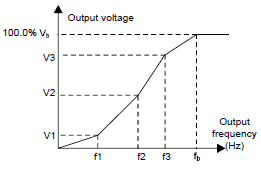
Goodrive35 series VFDs provide multi-dots V/F curve, the user can change the output V/F curve by setting the voltage and frequency of three middle dots. The whole curve is consisted of 5 dots. The starting dot is (0 Hz, 0 V), and the ending dot is (the basic frequency of the motor, the rated voltage of the motor). During the setting processing: 0≤f1≤f2≤f3≤the basic frequency of the motor; 0≤ V1≤ V2≤ V3≤the rated voltage of the motor.
Goodrive35 series VFDs provide special function code for SVPWM control mode which can improve the performance of SVPWM control by means of setting.
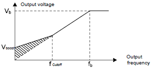
1. Torque boost
Torque boost function can effectively compensate for the performance of low speed torque during SVPWM control. Automatic torque boost has been set by default to enable the VFD to adjust the torque boost value based on the actual load conditions.
Note:
The torque boost takes effect only when the frequency is under the cap frequency of the boost. If the torque boost is too big, low frequency vibration or overcurrent fault may occur to the motor. If such situation occurs, lower the torque boost value.
2. Energy-saving running
In the actual operation, the VFD can search by itself to achieve a better effect point. The VFD can work with high effect to save energy.
Note:
This function is usually used in the cases where the load is light or empty. If the load transients frequently, this function is not appropriate to be selected.
3. V/F slips compensation gain
SVPWM control belongs to the open loop mode. If the load of the motor transients suddenly, the fluctuation of the rotation speed may occur. In the cases where the high accuracy speed is needed, slip compensation gain (internal output adjustment) can be set to compensate the speed change caused by load fluctuation.
Setting range of slip compensation gain: 0–200%, of which 100% corresponds to rated slip frequency.
Note: Rated slip frequency= (rated synchronous rotation speed of the motor-rated rotation speed of the motor) *number of pole pairs/60.
4. Vibration control
Motor vibration occurs frequently when applying SVPWM control mode in the cases where high power is needed. In order to settle this problem, Goodrive35 series VFDs add two function codes which are set to control the vibration factors. The user can set the corresponding function code according to the vibration frequency.
Note: Bigger the set value, more effective is the control. If the set value is too big, overcurrent may occur to the VFD.
User-defined V/F curve (V/F separation) function
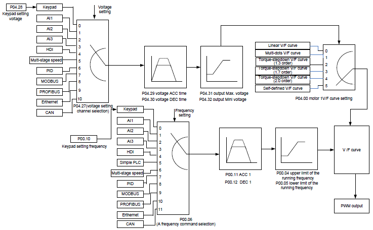
When the user selects the user-defined V/F curve function in Goodrive35 series VFDs, they can set the reference channel of voltage and frequency and the corresponding ACC/DEC time, or the two can be combined to form a real-time curve.
Note: The application of V/F curve separation can be used in many cases with various kinds of power supply of the VFD. But the users should set and adjust the parameters with caution. Incorrect parameters may cause damage to the VFD.
Function code | Name | Detailed instruction of parameters | Default value |
P00.00 | Speed control mode | 0: Sensorless vector control mode 1 1: Sensorless vector control mode 2 2: SVPWM control 3: Closed-loop vector control mode | 2 |
P00.03 | Max. output frequency | P00.04–400.00 Hz | 50.00 Hz |
P00.04 | Upper limit of running frequency | P00.05–P00.03 | 50.00 Hz |
P00.05 | Lower limit of running frequency | 0.00 Hz–P00.04 | 0.00 Hz |
P00.11 | ACC time 1 | 0.0–3600.0 s | Depend on model |
P00.12 | DEC time 1 | 0.0–3600.0 s | Depend on model |
P02.00 | Motor type 1 | 0: Asynchronous motor 1: Synchronous motor | 1 |
P02.02 | Rated frequency of asynchronous motor 1 | 0.01 Hz–P00.03 (max. output frequency) | 50.00 |
P02.04 | Rated voltage of asynchronous motor 1 | 0–1200 V | Depend on model |
P04.00 | Motor 1 V/F curve setting | 0: Straight line V/F curve 1: Multi-dots V/F curve 2: 1.3th power low torque V/F curve 3: 1.7th power low torque V/F curve 4: 2.0th power low torque V/F curve 5: Customized V/F (V/F separation) | 0 |
P04.01 | Torque boost of motor 1 | 0.0%: (automatic) 0.1%–10.0% | 0.0% |
P04.02 | Torque boost close of motor 1 | 0.0%–50.0% (rated frequency of motor 1 frequency) | 20.0% |
P04.03 | V/F frequency 1 of motor 1 | 0.00 Hz–P04.05 | 0.00 Hz |
P04.04 | V/F voltage 1 of motor 1 | 0.0%–110.0% | 00.0% |
P04.05 | V/F frequency 2 of motor 1 | P04.03–P04.07 | 00.00 Hz |
P04.06 | V/F voltage 2 of motor 1 | 0.0%–110.0% | 00.0% |
P04.07 | V/F frequency 3 of motor 1 | P04.05–P02.02 or P04.05–P02.16 | 00.00 Hz |
P04.08 | V/F voltage 3 of motor 1 | 0.0%–110.0% | 00.0% |
P04.09 | V/F slip compensation gain of motor 1 | 0.0–200.0% | 100.0% |
P04.10 | Vibration control factor at low frequency of motor 1 | 0–100 | 10 |
P04.11 | Vibration control factor at high frequency of motor 1 | 0–100 | 10 |
P04.12 | Vibration control threshold of motor 1 | 0.00 Hz–P00.03 (max. output frequency) | 30.00 Hz |
P04.13 | Motor 2 V/F curve setting | 0: Straight line V/F curve 1: Multi-dots V/F curve 2: 1.3th power low torque V/F curve 3: 1.7th power low torque V/F curve 4: 2.0th power low torque V/F curve 5: Customized V/F (V/F separation) | 0 |
P04.14 | Torque boost of motor 2 | 0.0%: (automatic) 0.1%–10.0% | 0.0% |
P04.15 | Torque boost close of motor 2 | 0.0%–50.0% (rated frequency of motor 1) | 20.0% |
P04.16 | V/F frequency 1 of motor 2 | 0.00 Hz–P04.18 | 0.00 Hz |
P04.17 | V/F voltage 1 of motor 2 | 0.0%–110.0% | 00.0% |
P04.18 | V/F frequency 2 of motor 2 | P04.16–P04.20 | 00.00 Hz |
P04.19 | V/F voltage 2 of motor 2 | 0.0%–110.0% | 00.0% |
P04.20 | V/F frequency 3 of motor 2 | P04.18–P12.02 (rated frequency of AM 2) or P04.18–P12.16 (rated frequency of SM 2) | 00.00 Hz |
P04.21 | V/F voltage 3 of motor 2 | 0.0%–110.0% | 00.0% |
P04.22 | V/F slip compensation gain of motor 2 | 0.0–200.0% | 100.0% |
P04.23 | Vibration control factor at low frequency of motor 2 | 0–100 | 10 |
P04.24 | Vibration control factor at high frequency of motor 2 | 0–100 | 10 |
P04.25 | Vibration control threshold of motor 2 | 0.00 Hz–P00.03 (max. output frequency) | 30.00 Hz |
P04.26 | Energy-saving operation | 0: No action 1: Automatic energy-saving running | 0 |
P04.27 | Voltage setting | 0: Keypad: the output voltage is determined by P04.28. 1: AI1; 2: AI2; 3: AI3; 4: HDI1; 5: Multi-step speed; 6: PID; 7: Modbus communication; 8: PROFIBUS/CANopen communication; 9: Ethernet communication (reserved) 10: Reserved | 0 |
P04.28 | Keypad setting voltage | 0.0%–100.0% (rated voltage of motor) | 100.0% |
P04.29 | Voltage increasing time | 0.0–3600.0s | 5.0 s |
P04.30 | Voltage decreasing time | 0.0–3600.0s | 5.0 s |
P04.31 | Maximum output voltage | P04.32–100.0% (rated voltage of motor) | 100.0% |
P04.32 | Minimum output voltage | 0.0%–P04.31 (rated voltage of motor) | 0.0% |