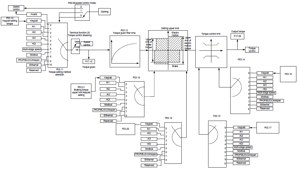
Goodrive35 series VFDs support two kinds of control mode: torque control and rotation speed control. The core of rotation speed is that the whole control focuses on the stable speed and ensures the setting speed is the same as the actual running speed. The Max Load should be in the range of the torque limit. The core of torque control is that the whole control focus on the stable torque and ensures the setting torque is the same as the actual output torque. At the same time, the output frequency is among the upper limit or the lower limit.
Function code | Name | Detailed instruction of parameters | Default value |
P00.00 | Speed control mode | 0: Sensorless vector control mode 1 1: Sensorless vector control mode 2 2: SVPWM control 3: Closed-loop vector control mode | 2 |
P03.11 | Torque setting method | 0: Torque control is invalid 1: Keypad setting torque (P03.11) 2: Analog AI1 setting torque (100% corresponds to three times of the rated current of the motor) 3: Analog AI2 setting torque (the same as above) 4: Analog AI3 setting torque (the same as above) 5: Pulse frequency HDI setting torque (the same as above) 6: Multi-step torque setting (the same as above) 7: Modbus communication setting torque (the same as above) 8: PROFIBUS/CANopen communication setting torque (the same as above) 9: Ethernet communication setting torque (the same as above) 10: Reserved | 0 |
P03.12 | Keypad setting torque | -300.0%–300.0% (rated current of the motor) | 10.0% |
P03.13 | Torque reference filter time | 0.000–10.000 s | 0.100s |
P03.14 | Upper frequency of forward rotation in vector control | 0: Keypad (P03.16) 1: AI1 (100% corresponds to max. frequency) 2: AI2 (the same as above) 3: AI3 (the same as above) 4: Pulse frequency HDI (the same as above) 5: Multi-step (the same as above) 6: Modbus communication (the same as above) 7: PROFIBUS/CANopen communication (the same as above) 8: Ethernet communication (the same as above) | 0 |
P03.15 | Upper frequency of reverse rotation in vector control | 0: Keypad (P03.17) 1: AI1 (100% corresponds to max. frequency) 2: AI2 (the same as above) 3: AI3 (the same as above) 4: Pulse frequency HDI (the same as above) 5: Multi-step (the same as above) 6: Modbus communication (the same as above) 7: PROFIBUS/CANopen communication (the same as above) 8: Ethernet communication (the same as above) | 0 |
P03.16 | Keypad setting for upper frequency of forward rotation | 0.00 Hz–P00.03 (max. output frequency) | 50.00 Hz |
P03.17 | Keypad setting for upper frequency of reverse rotation | 0.00 Hz–P00.03 (max. output frequency) | 50.00 Hz |
P03.18 | Upper electromotion torque source | 0: Keypad setting upper-limit frequency (P03.20) 1: AI1 (100% corresponds to three times of the rated current of the motor) 2: AI2 (the same as above) 3: AI3 (the same as above) 4: HDI (the same as above) 5: Modbus communication (the same as above) 6: PROFIBUS/CANopen communication (the same as above) 7: Ethernet communication (the same as above) | 0 |
P03.19 | Upper brake torque source | 0: Keypad setting upper-limit frequency (P03.21) 1: AI1 (100% corresponds to three times of the rated current of the motor) 2: AI2 (the same as above) 3: AI3 (the same as above) 4: HDI (the same as above) 5: Modbus communication (the same as above) 6: PROFIBUS/CANopen communication (the same as above) 7: Ethernet communication (the same as above) | 0 |
P03.20 | Keypad setting of electromotion torque | 0.0–300.0% (rated current of the motor) | 180.0% |
P03.21 | Keypad setting of brake torque | 0.0–300.0% (rated current of the motor) | 180.0% |
P17.09 | Output torque | -250.0–250.0% | 0.0% |
P17.15 | Torque reference | -300.0–300.0% (rated current of the motor) | 0.0% |