The start-up and stop control of the VFD includes three states: start after the running command during normal powering on, start after the restarting function becomes valid during normal powering on and start after the automatic fault reset.
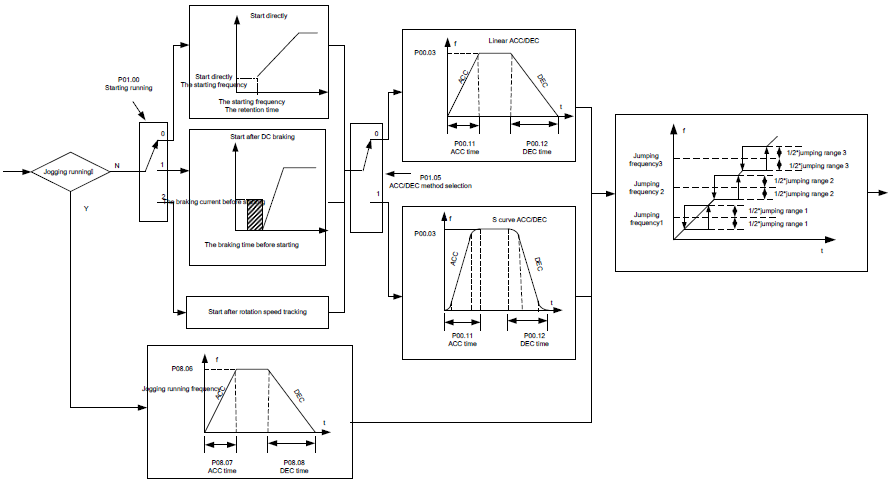
There are three starting modes for the VFD: start from the starting frequency directly, start after the AC brake and start after the rotation speed tracking. The user can select according to different situations to meet their needs.
For the load with big inertia, especially in the cases where the reverse rotation may occur, it is better to select starting after DC brake and then starting after rotation speed tracking.
Note: It is recommended to use the direct starting to drive synchronous motor.
1. The starting logic figure of starting after the running command during the normal powering on.
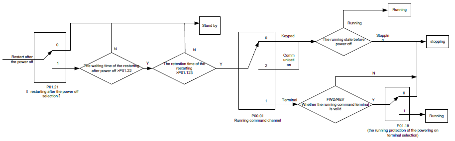
2. The starting logic figure of starting after the restarting function becomes valid during the normal powering on.
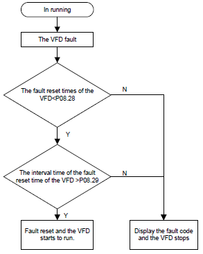
3. The starting logic figure of starting after the automatic fault reset.
Relative parameters list:
Function code | Name | Detailed instruction of parameters | Default value |
P00.01 | Run command channel | 0: Keypad running command (LED off) 1: Terminal running command channel (LED flickering) 2: Communication running command channel (LED on) | 0 |
P00.11 | ACC time 1 | 0.0–3600.0 s | Depend on model |
P00.12 | DEC time 1 | 0.0–3600.0 s | Depend on model |
P01.00 | Start mode | 0: Start-up directly 1: Start-up after DC brake 2: Start-up after rotation speed tracking | 0 |
P01.01 | Starting frequency of direct start | 0.00–50.00 Hz | 0.00 Hz |
P01.02 | Retention time of the starting frequency | 0.0–50.00 s | 0.00s |
P01.03 | The brake current before starting | 0.0–100.0% | 0.0% |
P01.04 | The brake time before starting | 0.0–30.0 s | 0.0s |
P01.05 | ACC/DEC selection | 0: Linear type 1: S curve | 0 |
P01.06 | ACC time of the starting step of S curve | 0.0–50.0s | 0.1s |
P01.07 | DEC time of the ending step of S curve | 0.0–50.0s | 0.1s |
P01.08 | Stop mode | 0: Decelerate to stop 1: Coast to stop | 0 |
P01.09 | Starting frequency of DC brake | 0.00 Hz–P00.03 (max. output frequency) | 0.00 Hz |
P01.10 | Waiting time of DC brake | 0.00–30.00 s | 0.00s |
P01.11 | DC brake current | 0.0–100.0% | 0.0% |
P01.12 | DC brake time | 0.0–50.0 s | 0.0 s |
P01.13 | Dead time of FWD/REV rotation | 0.0–3600.0 s | 0.0 s |
P01.14 | Shifting between FWD/REV rotation | 0: Switch after zero frequency 1: Switch after the starting frequency | 0 |
P01.15 | Stopping speed | 0.00–100.00 Hz | 0.20 Hz |
P01.16 | Detection of stopping speed | 0: Speed setting (the only detection method in SVPWM mode) 1: Speed detecting value | 0 |
P01.18 | Terminal running protection when powering on | 0: The terminal running command is invalid when powering on 1: The terminal running command is valid when powering on | 0 |
P01.19 | Action if running frequency< lower limit frequency (valid >0) | 0: Run at the lower-limit frequency 1: Stop 2: Hibernation 3: Run at zero frequency | 0 |
P01.20 | Hibernation restore delay time | 0.0–3600.0s (valid when P01.19=2) | 0.0s |
P01.21 | Restart after power off | 0: Disable 1: Enable | 0 |
P01.22 | The waiting time of restart after power off | 0.0–3600.0 s (valid when P01.21=1) | 1.0s |
P01.23 | Start delay time | 0.00–60.00 s | 0.00s |
P01.24 | Delay time of the stopping speed | 0.00–60.00 s | 0.00s |
P05.01–P05.09 | Digital input function selection | 1: Forward rotation operation 2: Reverse rotation operation 4: Forward rotation jogging 5: Reverse rotation jogging 6: Coast to stop 7: Fault reset 8: Operation pause 21: ACC/DEC time option 1 22: ACC/DEC time option 2 30: ACC/DEC prohibition | |
P08.00 | ACC time 2 | 0.0–3600.0 s | Depend on model |
P08.01 | DEC time 2 | 0.0–3600.0 s | Depend on model |
P08.02 | ACC time 3 | 0.0–3600.0 s | Depend on model |
P08.03 | DEC time 3 | 0.0–3600.0 s | Depend on model |
P08.04 | ACC time 4 | 0.0–3600.0 s | Depend on model |
P08.05 | DEC time 4 | 0.0–3600.0 s | Depend on model |
P08.06 | Jogging frequency | 0.00–P00.03 (max. output frequency) | 5.00 Hz |
P08.07 | Jogging ACC time | 0.0–3600.0 s | Depend on model |
P08.08 | Jogging DEC time | 0.0–3600.0 s | Depend on model |
P08.28 | Fault reset times | 0–10 | 0 |
P08.29 | Interval time of automatic fault reset | 0.1–3200.0 s | 1.0 s |