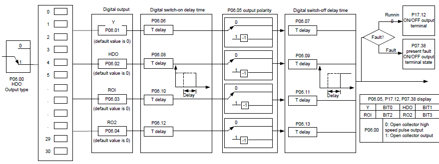
Goodrive35 series VFDs have 2 relay output terminals and 1 Y output terminal and 1 high speed pulse output terminal in the standard configuration. All functions of the digital input terminals are programmable by the function codes. Open collector pole input can be selected into high speed pulse input terminal or common switch input terminal by function code.
The below table is the option of the four function parameters and selecting the repeated output terminal function is allowed.
Set value | Function | Instructions |
0 | Invalid | The output terminal has no function. |
1 | Running | Output ON signal when the VFD is running and there is frequency output. |
2 | Forward running | Output ON signal when the VFD is running forward and there is frequency output. |
3 | Reverse running | Output ON signal when the VFD is running reverse and there is frequency output. |
4 | Jogging | Output ON signal when the VFD is jogging and there is frequency output. |
5 | VFD fault | Output ON signal when the VFD is in fault |
6 | FDT1 | Please refer to P08.32 and P08.33 for detailed information. |
7 | FDT2 | Please refer to P08.34 and P08.35 for detailed information. |
8 | Frequency arrival | Please refer to P08.36 for detailed information. |
9 | Zero-speed running | Output ON signal when the output frequency and given frequency of the VFD is 0 at the same time. |
10 | Upper-limit frequency arrival | Output ON signal when the running frequency of the VFD is the upper limit frequency. |
11 | Upper-limit frequency arrival | Output ON signal when the running frequency of the VFD is the lower limit frequency. |
12 | Ready to run | When the main circuit and the control circuit are established and the protection function of the VFD is not active. The VFD is in the running state and it will output ON signal. |
13 | Pre-exciting | Output ON signal when the VFD is in the pre-exciting state. |
14 | Overload pre-alarm | Output ON signal if the VFD is beyond the pre-alarm point. Refer to P11.08–P11.10 for the detailed instruction. |
15 | Underload pre-alarm | Output ON signal if the VFD is beyond the pre-alarm point. Refer to P11.11–P11.12 for the detailed instruction. |
16 | Simple PLC stage completion | Output signal if the simple PLC stage is completed. |
17 | Simple PLC cycle completion | Output signal if the 1 simple PLC cycle is completed. |
23 | Modbus communication virtual terminal output | Output corresponding signal according to the setting value of Modbus. Output ON signal if the setting value is 1 and output OFF signal if the setting value is 0. |
24 | POROFIBUS/CANopen communication virtual terminal output | Output corresponding signal according to the setting value of PROFIBUS/CANOPEN. Output ON signal if the setting value is 1 and output OFF signal if the setting value is 0. |
25 | Ethernet communication virtual terminal output | Output the corresponding signal according to the Ethernet signal. Output ON when setting as1 and output OFF when setting as 0. |
26 | Bus voltage established | Output ON according to the establishment of bus voltage |
27–29 | Reserved | |
30 | Positioning finished | Output ON when the positioning is finished |
31 | Spindle returning finished | Output ON when the returning is finished |
32 | Spindle scaling finished | Output ON when the scaling is finished |
33 | Speed limiting | Output ON when the speed is the upper or lower limit |
34 | Low bus voltage | Output ON when the value is below P8.27 |
35 | Underload stopping output | If enabling bit of P08.26 is valid, and it is in underload state, ON signal will be output |
36 | Speed/position switching finished | When the speed is switched to position control, output ON signal |
Relative parameters list:
Function code | Name | Detailed instruction of parameters | Default value |
P06.00 | HDO output | 0: Open collector pole high speed pulse output 1: Open collector pole output | 0 |
P06.01 | Y1 output | 0: Invalid 1: In operation 2: Forward rotation operation 3: Reverse rotation operation 4: Jogging operation 5: VFD fault 6: Frequency degree test FDT1 7: Frequency degree test FDT2 8: Frequency arrival 9: Zero speed running 10: Upper limit frequency arrival 11: Lower limit frequency arrival 12: Ready for operation 13: In pre-exciting 14: Overload pre-alarm 15: Underload pre-alarm 16: Completion of simple PLC stage 17: Completion of simple PLC cycle 18–22: Reserved 23: Modbus communication virtual terminals output 24: PROFIBUS/CANopen communication virtual terminals output 25: Ethernet communication virtual terminals output 26: Bus voltage established 27: Reserved 28: Pulse superposing 29: Reserved 30: Positioning finished 31: Spindle zeroing finished 32: Spindle scaling finished 33: Speed limiting 34: Bus voltage too low 35: Bus undervoltage stop state output 36: Speed/position control switching finished 37–40: Reserved | 0 |
P06.02 | HDO output | 0 | |
P06.03 | Relay RO1 output | 1 | |
P06.04 | Relay RO2 output | 5 | |
P06.05 | Polarity of output terminals | 0x00–0x0F | 0x00 |
P06.06 | Y1 switch-on delay time | 0.000–50.000 s | 0.000 s |
P06.07 | Y1 switch-off delay time | 0.000–50.000 s | 0.000 s |
P06.08 | HDO switch-on delay | 0.000–50.000 s (valid only when P06.00=1) | 0.000 s |
P06.09 | HDO switch-off delay | 0.000–50.000 s (valid only when P06.00=1) | 0.000 s |
P06.10 | RO1 switch-on delay | 0.000–50.000 s | 0.000 s |
P06.11 | RO1 switch-off delay | 0.000–50.000 s | 0.000 s |
P06.12 | RO2 switch-on delay | 0.000–50.000 s | 0.000 s |
P06.13 | RO2 switch-off delay | 0.000–50.000 s | 0.000 s |
P07.40 | Output terminal state at present fault | 0 | |
P17.13 | Digital output terminals state | 0 |