Goodrive300 series VFDs can set the frequency by various means. The given channel can be divided into main given channel and assistant given channel.
There are two mian given channels: A frequency given channel and B frequency given channel. These two given channels can carry out mutual simple math calculation between each other. And the given channels can be shifted dynamically through set multi-funciton terminals.
There are three assistane given channels: keypad UP/DOWN input, terminals UP/DOWN switch input and digital potentiometer input. The three ways equal to the effect of input UP/DOWN given in internal assistant given of the VFD. The user can enable the given method and the effect of the method to the frequency given by setting function codes.
The actual given of the VFD is comsisted of main given channel and assistant given channel.
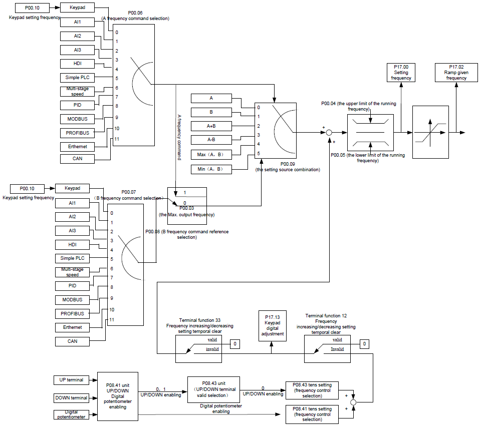
Goodrive300 series VFDs support the shifting between different given channels, and the detailed shifting rules are as below:
Current given channel P00.09 | Multi-function terminal function 13 Switch from A channel to B channel | Multi-function terminal function 14 Switch from combination setting to A channel | Multi-function terminal function 15 Switch from combination setting to B channel |
A | B | / | / |
B | A | / | / |
A+B | / | A | B |
A-B | / | A | B |
Max(A,B) | / | A | B |
Min(A,B) | / | A | B |
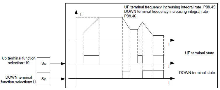
When select multi-function terminal UP (10) and DOWN (11) to set the internal assistant frequency, P08.44 and P08.45 can be set to increase or decrease the set frequency quickly.
Related parameters
Function code | Name | Detailed instruction of parameters | Default value |
P00.03 | Max. output frequency | P00.04–400.00Hz | 50.00Hz |
P00.04 | Upper limit of the running frequency | P00.05–P00.03 | 50.00Hz |
P00.05 | Lower limit of the running frequency | 0.00Hz–P00.04 | 0.00Hz |
P00.06 | A frequency command | 0: Keypad 1: AI1 2: AI2 3: AI3 4: High-speed pulse HDI 5: Simple PLC program 6: Multi-step speed running 7: PID control 8: Modbus communication 9: PROFIBUS/CANopen communication 10: Ethernet communication 11: Reserved | 0 |
P00.07 | B frequency command | 0 | |
P00.08 | B frequency command reference | 0: Max. output frequency 1: A frequency command | 0 |
P00.09 | Combination of setting sources | 0: A 1: B 2: (A+B) combination 3: (A-B) combination 4: Max(A,B) combination 5: Min(A,B) combination | 0 |
P05.01–P05.09 | Multi-function digital input terminals (S1–S8, HDI) function selection | 10: Increasing frequency setting (UP) 11: Decreasing frequency setting (DOWN) 12: Cancel the frequency change setting 13: Shift between A setting and B setting 14: Shift between combination setting and A setting 15: Shift between combination setting and B setting | |
P08.42 | Keypad data control | 0x000–0x1223 LED ones: frequency enable selection 0: Both ∧/∨ keys and digital potentiometer adjustments are valid 1: Only ∧/∨ keys adjustment is valid 2: Only digital potentiometer adjustments is valid 3: Neither ∧/∨ keys nor digital potentiometer adjustments are valid LED tens: frequency control selection 0: Only valid when P00.06=0 or P00.07=0 1: Valid for all frequency setting manner 2: Invalid for multi-step speed when multi-step speed has the priority LED hundreds: action selection during stopping 0: Setting is valid 1: Valid during running, cleared after stopping 2: Valid during running, cleared after receiving the stop command LED thousands: ∧/∨ keys and digital potentiometer Integral function 0: The Integral function is valid 1: The Integral function is invalid | 0x0000 |
P08.43 | Integral ratio of the keypad potentiometer | 0.01–10.00s | 0.10s |
P08.44 | UP/DOWN terminals control | 0x00–0x221 LED ones: frequency control selection 0: UP/DOWN terminals setting valid 1: UP/DOWN terminals setting valid LED tens: frequency control selection 0: Only valid when P00.06=0 or P00.07=0 1: All frequency means are valid 2: When the multi-step are priority, it is invalid to the multi-step LED hundreds: action selection when stop 0: Setting valid 1: Valid in the running, clear after stop 2: Valid in the running, clear after receiving the stop commands | 0x000 |
P08.45 | UP terminals frequency changing ratio | 0.01–50.00Hz/s | 0.50 Hz/s |
P08.46 | DOWN terminals frequency changing ratio | 0.01–50.00 Hz/s | 0.50 Hz/s |
P17.00 | Setting frequency | Display current set frequency of the VFD Range: 0.00Hz–P00.03 | 0.00Hz |
P17.02 | Ramp reference frequency | Display current ramp given frequency of the VFD. Range: 0.00Hz–P00.03 | 0.00Hz |
P17.14 | Digital adjustment | Display the adjustment through the keypad of the VFD. Range: 0.00Hz–P00.03 | 0.00V |