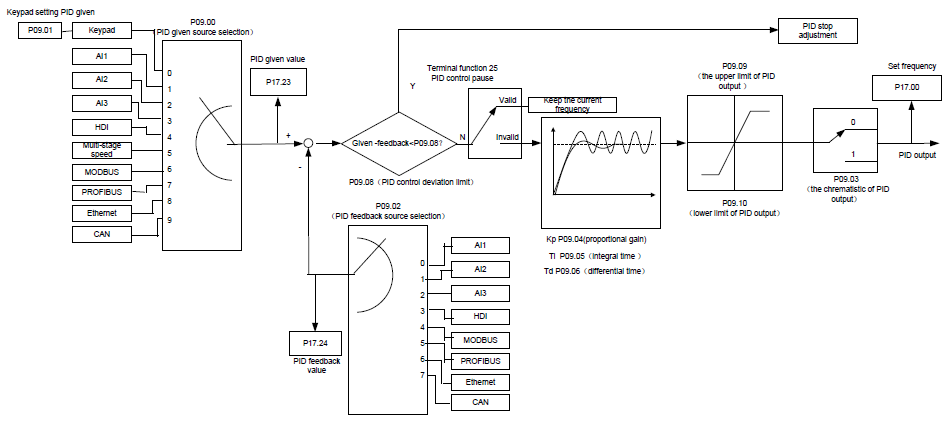
PID control is commonly used to control the procedure through the controlled procedure. Adjust the output frequency by proportional, integral, differential operation with the dispersion of the target signals to stabilize the value on the target. It is possible to apply to the flow, pressure and temperature control. Figure of basic control is as below:
Simple illustration of the PID control operation and adjustment:
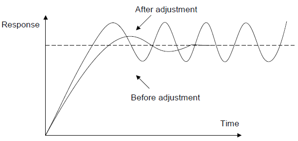
Proportional adjustment (Kp): when there is an error between the feedback and the reference, a proportional adjustment will be output. If the error is constant, the adjustment will be constant, too. Proportional adjustment can respond to the feedback change quickly, but it cannot realize non-fault control. The gain will increase with the adjustment speed, but too much gain may cause vibration. The adjustment method is: set a long integral time and derivative time to 0 first. Secondly make the system run by proportional adjustment and change the reference. And then watch the error of the feedback signal and the reference. If the static error is available (for example, increasing the reference, the feedback will be less than the reference after a stable system), continue to increase the gain, vice versa. Repeat the action until the static error achieves a little value.
Integral time (Ti): the output adjustment will accumulate if there is an error between the feedback and the reference. The adjustment will keep on increasing until the error disappears. If the error is existent all the time, the integration adjustor can cancel the static error effectively. Vibration may occur as a result of unstable system caused by repeated over-adjustment if the integration adjustor is too strong. The features of this kind of vibration are: the fluctuating feedback signal (around the reference) and increasing traverse range will cause vibration. Adjust the integral time parameter from a big value to a little one to change the integral time and monitor the result until a stable system speed is available.
Derivative time (Td): when the error between the feedback and the reference, a proportional adjustment will be output. The adjustment only depends on the direction and value of the error change other than the error itself. The derivation adjustment controls the change of feedback signals according to the changing trend when it fluctuates. Because the derivation may enlarge the interference to the system, especially the frequent-changing interference, please use it carefully.
When P00.06, P00. 07=7 or P04.27=6, the running mode of the VFD is procedure PID control.
7.15.1 General steps of PID parameters setting:
a Ensure the gain P
When ensure the gain P, firstly cancel the PID integration and derivation (set Ti=0 and Td=0, see the PID parameter setting for detailed information) to make proportional adjustment is the only method to PID. Set the input as 60%–70% of the permitted Max. Value and increase gain P from 0 until the system vibration occurs, vice versa, and record the PID value and set it to 60%–70% of the current value. Then the gain P commission is finished.
b Ensure the integral time Ti
After ensuring the gain P, set an original value of a bigger integral time and decrease it until the system vibration occurs, vice versa, until the system vibration disappear. Record the Ti and set the integral time to 150%–180% of the current value. Then integral time commission is finished.
c Ensure the derivative time Td
Generally, it is not necessary to set Td which is 0.
If it needs to be set, set it to 30% of the value without vibration via the same method with P and Ti.
d Commission the system with and without load and then adjust the PID parameter until it is available.
7.15.2 PID inching
After setting the PID control parameters, inching is possible by following means:
Control the overshoot
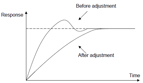
Shorten the derivative time and prolong the integral time when overshoot occurs.
Achieve the stable state as soon as possible
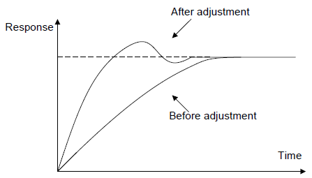
Shorten the integral time (Ti) and prolong the derivative time (Td) even the overshoot occurs, but the control should be stable as soon as possible.
Control long vibration
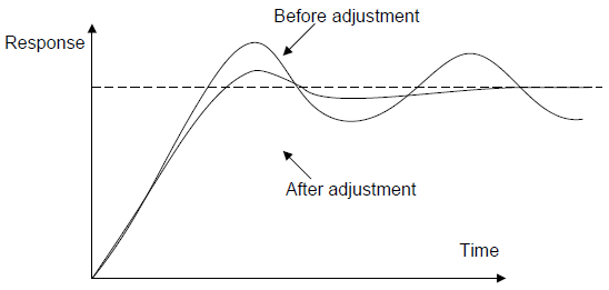
If the vibration periods are longer than the set value of integral time (Ti), it is necessary to prolong the integral time (Ti) to control the vibration for the strong integration.
Control short vibration
Short vibration period and the same set value with the derivative time (Td) mean that the derivative time is strong. Shortening the derivative time (Td) can control the vibration. When setting the derivative time as 0.00(ire no derivation control) is useless to control the vibration, decrease the gain.
Related parameters
Function code | Name | Detailed instruction of parameters | Default value |
P09.00 | PID reference source | 0: Keypad (P09.01) 1: AI1 2: AI2 3: AI3 4: HDI 5: Multi-step speed set 6: Modbus communication set 7: PROFIBUS/CANopen communication set 8: Ethernet communication set 9: Reserved | 0 |
P09.01 | Keypad PID preset | -100.0%–100.0% | 0.0% |
P09.02 | PID feedback source | 0: AI1 1: AI2 2: AI3 3: HDI 4: Modbus communication feedback 5: PROFIBUS/CANopen communication feedback 6: Ethernet communication feedback 7: Reserve | 0 |
P09.03 | PID output feature | 0: PID output is positive 1: PID output is negative | 0 |
P09.04 | Proportional gain (Kp) | 0.00–100.00 | 1.00 |
P09.05 | Intergal time (Ti) | 0.00–10.00s | 0.10s |
P09.06 | Differential time (Td) | 0.00–10.00s | 0.00s |
P09.07 | Sampling cycle (T) | 0.000–10.000s | 0.100s |
P09.08 | PID control deviation limit | 0.0–100.0% | 0.0% |
P09.09 | Output upper limit of PID | P09.10–100.0% (Max. frequency or the Max. voltage) | 100.0% |
P09.10 | Output lower limit of PID | -100.0%–P09.09 (Max. frequency or the Max. voltage) | 0.0% |
P09.11 | Detection value of feedback offline | 0.0–100.0% | 0.0% |
P09.12 | Detection time of feedback offline | 0.0–3600.0s | 1.0s |
P09.13 | PID adjustment | 0x0000–0x1111 LED ones: 0: Keep on integral adjustment when the frequency achieves the upper and low limit; the integration shows the change between the reference and the feedback unless it reaches the internal integral limit. When the trend between the reference and the feedback changes, it needs more time to offset the impact of continuous working and the integration will change with the trend. 1: Stop integral adjustment when the frequency achieves the upper and low limit. If the integration keeps stable, and the trend between the reference and the feedback changes, the integration will change with the trend quickly. LED tens: P00.08 is 0 0: The same with the setting direction; if the output of PID adjustment is different from the current running direction, the internal will output 0 forcedly. 1: Opposite to the setting direction LED hundreds: P00.08 is 0 0: Limit to the maximum frequency 1: Limit to frequency A LED thousands: 0: A+B frequency, the buffer of A frequency is invalid 1: A+B frequency, the buffer of A frequency is valid ACC/DEC is determined by ACC time 4 of P08.04 | 0x0001 |
P17.00 | Setting frequency | 0.00Hz–P00.03 (Max. frequency) | 0.00Hz |
P17.23 | PID reference | -100.0–100.0% | 0.0% |
P17.24 | PID feedback | -100.0–100.0% | 0.0% |