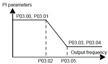
P03.00 | Speed loop proportional gain1 | The parameters P03.00–P03.05 only apply to vector control mode. Below the switching frequency 1 (P03.02), the speed loop PI parameters are: P03.00 and P03.01. Above the switching frequency 2 (P03.05), the speed loop PI parameters are: P03.03 and P03.04. PI parameters are gained according to the linear change of two groups of parameters. It is shown as below:
Setting the proportional coefficient and integral time of the adjustor can change the dynamic response performance of vector control speed loop. Increasing the proportional gain and decreasing the integral time can speed up the dynamic response of the speed loop. But too high proportional gain and too low integral time may cause system vibration and overshoot. Too low proportional gain may cause system vibration and speed static deviation. PI has a close relationship with the inertia of the system. Adjust on the base of PI according to different loads to meet various demands. Setting range of P03.00: 0– 200.0 Setting range of P03.01: 0.000– 10.000s Setting range of P03.02: 0.00Hz– P03.05 Setting range of P03.03: 0– 200.0 Setting range of P03.04: 0.000– 10.000s Setting range of P03.05: P03.02– P00.03 (Max. output frequency) | 20.0 | ○ |
P03.01 | Speed loop integral time 1 | 0.200s | ○ | |
P03.02 | Low switching frequency | 5.00Hz | ○ | |
P03.03 | Speed loop proportional gain 2 | 20.0 | ○ | |
P03.04 | Speed loop integral time 2 | 0.200s | ○ | |
P03.05 | High switching frequency | 10.00 Hz | ○ | |
P03.06 | Speed loop output filter | 0–8 (corresponds to 0–28/10ms) | 0 | ○ |
P03.07 | Compen- sation coefficient of electromo- tion slip | Slip compensation coefficient is used to adjust the slip frequency of the vector control and improve the speed control accuracy of the system. Adjusting the parameter properly can control the speed steady-state error. Setting range: 50%–200% | 100% | ○ |
P03.08 | Compensation coefficient of braking slip | 100% | ○ | |
P03.09 | Current loop percentage coefficient P | Note: 1 These two parameters adjust the PI adjustment parameter of the current loop which affects the dynamic response speed and control accuracy directly. Generally, users do not need to change the default value. 2 Only apply to the vector control mode without PG 0 (P00.00=0). Setting range: 0– 65535 | 1000 | ○ |
P03.10 | Current loop integral coefficient 1 | 1000 | ○ | |
P03.11 | Torque setting method | This parameter is used to enable the torque control mode, and set the torque. 0: Torque control is invalid 1: Keypad setting torque (P03.12) 2: Analog AI1 setting torque 3: Analog AI2 setting torque 4: Analog AI3 setting torque 5: Pulse frequency HDI setting torque 6: Multi-step torque setting 7: Modbus communication setting torque 8: PROFIBUS\CANopen communication setting torque 9: Ethernet communication setting torque 10: Reserved Note: For setting modes of 2–10, 100% corresponds to three times of the rated current of the motor. | 0 | ○ |
P03.12 | Keypad setting torque | Setting range: -300.0%–300.0% (rated current of the motor) | 50.0% | ○ |
P03.13 | Torque reference filter time | 0.000–10.000s | 0.010s | ○ |
P03.14 | Upper frequency of forward rotation in vector control | 0: Keypad (P03.16 sets P03.14, P03.17 sets P03.15) 1: AI1 2: AI2 3: AI3 4: Pulse frequency HDI setting upper-limit frequency 5: Multi-step setting upper-limit frequency 6: Modbus communication setting upper-limit frequency 7: PROFIBUS\CANopen communication setting upper-limit frequency 8: Ethernet communication setting upper-limit frequency 9: Reserved Note: For setting modes of 1–9, 100% corresponds to the maximum frequency. | 0 | ○ |
P03.15 | Upper frequency of reverse rotation in vector control | 0 | ○ | |
P03.16 | Keypad setting for upper frequency of forward rotation | This function is used to set the upper limit of the frequency. P03.16 sets the value of P03.14; P03.17 sets the value of P03.15. Setting range: 0.00 Hz–P00.03 (Max. output frequency) | 50.00 Hz | ○ |
P03.17 | Keypad setting for upper frequency of reverse rotation | 50.00 Hz | ○ | |
P03.18 | Upper electro- motion torque source | This function code is used to select the electromotion and braking torque upper-limit setting source selection. 0: Keypad setting upper-limit frequency(P03.20 sets P03.18, P03.21 sets P03.19) 1: AI1 2: AI2 3: AI3 4: HDI 5: Modbus communication 6: PROFIBUS\CANopen communication 7: Ethernet communication 8: Reserved Note: For setting modes of 1–9, 100% corresponds to three times of the motor current. | 0 | ○ |
P03.19 | Upper braking torque source | 0 | ○ | |
P03.20 | Keypad setting of electro- motion torque | The function code is used to set the limit of the torque. Setting range: 0.0–300.0% (motor rated current) | 180.0% | ○ |
P03.21 | Keypad setting of braking torque | 180.0% | ○ | |
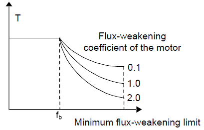
P03.22 | Weake- ning coeffi- cient in constant power zone | The usage of motor in weakening control.
Function code P03.22 and P03.23 are effective at constant power. The motor will enter into the weakening state when the motor runs at rated speed. Change the weakening curve by modifying the weakening control coefficienct. The bigger the weakening control coefficienct is, the steeper the weak curve is. Setting range of P03.22: 0.1 –2.0 Setting range of P03.23: 10%– 100% | 0.3 | ○ |
P03.23 | Lowest weake- ning point in constant power zone | 20% | ○ | |
P03.24 | Max. voltage limit | P03.24 set the Max. Voltage of the VFD, which is dependent on the site situation. Setting range: 0.0–120.0% | 100.0% | ◎ |
P03.25 | Pre-exciting time | Preactivate the motor when the VFD starts up. Build up a magnetic field inside the VFD to improve the torque performance during the starting process. The setting time: 0.000– 10.000s | 0.300s | ○ |
P03.26 | Weak magnetic propor- tional gain | 0–8000 Note: P03.24–P03.26 are invalid for the vector mode. | 1000 | ○ |
P03.27 | Vector control speed | 0: Display the actual value 1: Display the setting value | 0 | ○ |
P03.28 | Compen- sation coefficient of static friction | 0.0–100.0% Adjust P03.28 to compensate the coefficient of static friction. Only valid when setting in 1Hz. | 0.0% | ○ |
P03.29 | Compen- sation coefficient of dynamic friction | 0.0–100.0% Adjust P03.29 to compensate the coefficient of static friction. Only valid when setting in 1Hz. | 0.0% | ○ |