Function code | Name | Detailed instruction of parameters | Default value | Modify |
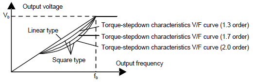
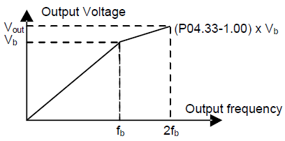
P04.00 | Motor 1V/F curve setting | These function codes define the V/F curve of Goodrive300 motor 1 to meet the need of different loads. 0: Straight line V/F curve;applying to the constant torque load 1: Multi-dots V/F curve 2: 1.3th power low torque V/F curve 3: 1.7th power low torque V/F curve 4: 2.0th power low torque V/F curve Curves 2–4 apply to the torque loads such as fans and water pumps. Users can adjust according to the features of the loads to achieve a best energy-consuming effect. 5: Customized V/F(V/F separation); on this mode, V and F can be separated from adjusted through the frequency given channel set by P00.06 or the voltage given channel set by P04.27 to change the feature of the curve. Note: Vb in the below picture is the motor rated voltage and fb is the motor rated frequency.
| 0 | ◎ |
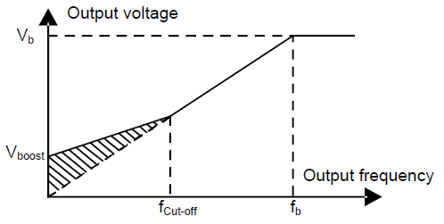
P04.01 | Torque boost of motor 1 | Boost compensation can be given to the output voltage for compensating the features of low frequency torque. P04.01 is for the Max. Output voltage Vb. P04.02 defines the percentage of closing frequency of manual torque to fb. Torque boost can improve the features of low frequency torque of V/F. Torque boost should be selected according to the load. The bigger the load is, the bigger the boost is. Too big torque boost is inappropriate because the motor will run with over-magnetic, and the current of the VFD will increase to raise the temperature of the VFD and decrease the efficiency. When the torque boost is set to 0.0%, the VFD is automatic torque boost. Torque boost threshold: under the threshold, the torque boost is valid, but over the threshold, the torque boost is invalid.
Setting range of P04.01: 0.0%: (automatic) 0.1%–10.0% Setting range of P04.02: 0.0%–50.0% | 0.0% | ○ |
P04.02 | Torque boost close of motor 1 | 20.0% | ○ | |
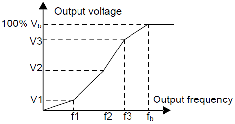
P04.03 | V/F frequency 1 of motor 1 | When P04.00 =1, the user can set V//F curve through P04.03–P04.08. V/F is generally set according to the load of the motor. Note:V1<V2<V3, f1<f2<f3. Too high low frequency voltage will heat the motor excessively or cause damage. The VFD may stall when overcurrent or overcurrent protection.
Setting range of P04.03: 0.00Hz–P04.05 Setting range of P04.04: 0.0%–110.0% Setting range of P04.05: P04.03– P04.07 Setting range of P04.06: 0.0%–110.0% (the rated voltage of motor 1) Setting range of P04.07: P04.05– P02.02 (the rated frequency of motor 1) or P04.05–P02.16 (the rated frequency of motor 1) Setting range of P04.08: 0.0%–110.0% (the rated voltage of motor 1) | 0.00Hz | ○ |
P04.04 | V/F voltgage 1 of motor 1 | 00.0% | ○ | |
P04.05 | V/F frequency 2 of motor 1 | 00.00 Hz | ○ | |
P04.06 | V/F voltgage 2 of motor 1 | 00.0% | ○ | |
P04.07 | V/F frequency 3 of motor 1 | 00.00 Hz | ○ | |
P04.08 | V/F voltage 3 of motor 1 | 00.0% | ○ | |
P04.09 | V/F slip compensation gain of motor 1 | This function code is used to compensate the change of the rotation speed caused by load during compensation SVPWM control to improve the rigidity of the motor. It can be set to the rated slip frequency of the motor which is counted as below: △f=fb-n×p/60 Of which, fb is the rated frequency of the motor, its function code is P02.02; n is the rated rotating speed of the motor and its function code is P02.03; p is the pole pair of the motor. 100.0% corresponds to the rated slip frequency△f. Setting range: 0.0–200.0% | 100.0% | ○ |
P04.10 | Vibration control factor at low frequency of motor 1 | In SVPWM control mode, current fluctuation may occur to the motor at some frequency, especially the motor with big power. The motor cannot run stably or overcurrent may occur. These phenomena can be canceled by adjusting this parameter. Setting range of P04.10: 0–100 Setting range of P04.11: 0–100 Setting range of P04.12: 0.00Hz–P00.03 (Max. frequency) | 10 | ○ |
P04.11 | Vibration control factor at high frequency of motor 1 | 10 | ○ | |
P04.12 | Vibration control threshold of motor 1 | 30.00 Hz | ○ | |
P04.13 | Motor 2 V/F curve setting | This group of parameters defines the V/F setting modes of Goodrive300 motor 2 to meet various requirements of different loads. See P04.00–P04.12 for the detailed function code instruction. Note: P04 group includess two sets of V/F parameters of the motor which cannot display simultaneously. Only the selected V/F parameter can be shown. The motor selection can be defined by terminals function "the shift between motor 1 and motor 2". | 0 | ◎ |
P04.14 | Torque boost of motor 2 | 0.0% | ○ | |
P04.15 | Torque boost close of motor 2 | 20.0% | ○ | |
P04.16 | V/F frequency 1 of motor 2 | 0.00Hz | ○ | |
P04.17 | V/F voltage 1 of motor 2 | 00.0% | ○ | |
P04.18 | V/F frequency 2 of motor 2 | 00.00 Hz | ○ | |
P04.19 | V/F voltage 2 of motor 2 | 00.0% | ○ | |
P04.20 | V/F frequency 3 of motor 2 | 00.00 Hz | ○ | |
P04.21 | V/F voltage 3 of motor 2 | 00.0% | ○ | |
P04.22 | V/F slip compensation gain of motor 2 | 100.0% | ○ | |
P04.23 | Vibration control factor at low frequency of motor 2 | In SVPWM control mode, current fluctuation may occur to the motor on some frequency, especially the motor with big power. The motor cannot run stably or overcurrent may occur. These phenomena can be canceled by adjusting this parameter. Setting range of P04.23: 0–100 Setting range of P04.24: 0–100 Setting range of P04.25: 0.00 Hz–P00.03 (Max. output frequency) | 10 | ○ |
P04.24 | Vibration control factor at high frequency of motor 2 | 10 | ○ | |
P04.25 | Vibration control threshold of motor 2 | 30.00 Hz | ○ | |
P04.26 | Energy-saving operation | 0: No operation 1: Automatic energy-saving operation Motors with light load will automatically adjust the output voltage to save energy. | 0 | ◎ |
P04.27 | Voltage setting | Select the output setting channel at V/F curve separation. 0: Keypad: the output voltage is determined by P04.28. 1: AI1 2: AI2 3: AI3 4: HDI 5: Multi-step speed 6: PID 7: Modbus communication 8: PROFIBUS/CANopen communication 9: Ethernet communication 10: Reserved Note: 100% corresponds to the rated voltage of the motor. | 0 | ○ |
P04.28 | Keypad setting voltage | The function code is the voltage displaying when the voltage is set through keypad. Setting range: 0.0%–100.0% | 100.0% | ○ |
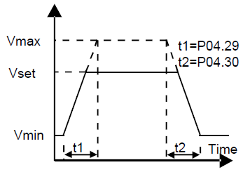
P04.29 | Voltage increasing time | Voltage increasing time is the time when the VFD accelerates from the output minimum voltage to the output maximum voltage. Voltage decreasing time is the time when the VFD decelerates from the output maximum voltage to the output minimum voltage. Setting range: 0.0–3600.0s | 5.0s | ○ |
P04.30 | Voltage decreasing time | 5.0s | ○ | |
P04.31 | Max. output voltage | Set the upper and low limit of the output voltage.
Setting range of P04.31: P04.32–100.0%(the rated voltage of the motor) Setting range of P04.32: 0.0%– P04.31(the rated voltage of the motor) | 100.0% | ◎ |
P04.32 | Min. output voltage | 0.0% | ◎ | |
P04.33 | Weaking coefficient at constant power | Used during field-weakening operation to adjust the output voltage of VFD in SVPWM mode. Note: Invalid in constant-torque mode.
Setting range of P04.33: 1.00–1.30 | 1.00 | ○ |