Function code | Name | Detailed instruction of parameters | Default value | Modify |
P06.00 | HDO output | The function selection of the high-speed pulse output terminals. 0: Open collector high speed pulse output: The Max.pulse frequency is 50.0kHz. See P06.27–P06.31 for detailed information of the related functions. 1: Open collector output. See P06.02 for detailed information of the related functions. | 0 | ◎ |
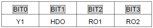
P06.01 | Y1 output | 0: Invalid 1: In operation 2: Forward rotation operation 3: Reverse rotation operation 4: Jogging operation 5: The VFD fault 6: Frequency degree test FDT1 7: Frequency degree test FDT2 8: Frequency arrival 9: Zero speed running 10: Upper limit frequency arrival 11: Lower limit frequency arrival 12: Ready for operation 13: Pre-magnetizing 14: Overload pre-alarm 15: Underload pre-alarm 16: Completion of simple PLC stage 17: Completion of simple PLC cycle 18: Set count value reached 19: Specified count value reached 20: External fault valid 21: Length arrival 22: Running time arrival 23: Modbus communication virtual terminals output 24: PROFIBUS/CANopen communication virtual terminals output 25: Ethernet communication virtual terminals output 26: Voltage establishment finished 27–30: Reserved | 0 | ○ |
P06.02 | HDO output | 0 | ○ | |
P06.03 | Relay RO1 output | 1 | ○ | |
P06.04 | Relay RO2 output | 5 | ○ | |
P06.05 | Polarity of output terminals | The function code is used to set the pole of the output terminal. When the current bit is set to 0, the input terminal is anode. When the current bit is set to 1, the input terminal is cathode.
Setting range: 00–0F | 00 | ○ |
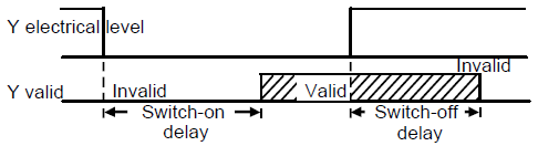
P06.06 | Y1 switch-on delay time | The function code defines the corresponding delay time of the electrical level change during the programmable terminal switching on and off.
Setting range: 0.000–50.000s Note: P06.08 and P06.08 are valid only when P06.00=1. | 0.000s | ○ |
P06.07 | Y1 switch-off delay time | 0.000s | ○ | |
P06.08 | HDO switch-on delay time | 0.000s | ○ | |
P06.09 | HDO switch-off delay time | 0.000s | ○ | |
P06.10 | RO1 switch-on delay time | 0.000s | ○ | |
P06.11 | RO1 switch-off delay time | 0.000s | ○ | |
P06.12 | RO2 switch-on delay time | 0.000s | ○ | |
P06.13 | RO2 switch-off delay time | 0.000s | ○ | |
P06.14 | AO1 output | 0: Running frequency 1: Set frequency 2: Ramp reference frequency 3: Running rotation speed (relative to 2 times the synchronous rotation speed of the motor) 4: Output current (relative to 2 times the rated current of the VFD) 5: Output current (relative to 2 times the rated current of the motor) 6: Output voltage (relative to 1.5 times the rated voltage of the VFD) 7: Output power (relative to 2 times the rated power of the motor) 8: Set torque value (relative to 2 times the rated torque of the motor) 9: Output torque (relative to 2 times the rated torque of the motor) 10: Analog AI1 input value 11: Analog AI2 input value 12: Analog AI3 input value 13: Input value of high-speed pulse HDI 14: Modbus communication set value 1 15: Modbus communication set value 2 16: Set value 1 of PROFIBUS/CANopen communication 17: Set value 2 of PROFIBUS/CANopen communication 18: Set value 1 of Ethernet communication 19: Set value 2 of Ethernet communication 20–21: Reserved 22: Torque current (corresponding to triple the rated current of the motor) 23: Ramp reference frequency (with sign) 24–30: Reserved | 0 | ○ |
P06.15 | AO2 output | 0 | ○ | |
P06.16 | HDO high-speed pulse output | 0 | ○ | |
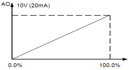
P06.17 | Lower output limit of AO1 | The above function codes define the relative relationship between the output value and analog output. When the output value exceeds the range of set maximum or minimum output, it will count according to the low-limit or upper-limit output. When the analog output is current output, 1mA equals to 0.5V. In different cases, the corresponding analog output of 100% of the output value is different. See each application for detailed information.
Setting range of P06.18: 0.00V–10.00V Setting range of P06.19: P06.17–100.0% Setting range of P06.20: 0.00V–10.00V Setting range of P06.21: 0.000s–10.000s Setting range of P06.22: -100.0%–P06.24 Setting range of P06.23: 0.00V–10.00V Setting range of P06.24: P06.22–100.0% Setting range of P06.25: 0.00V–10.00V Setting range of P06.26: 0.000s–10.000s Setting range of P06.27: -100.0%–P06.29 Setting range of P06.28: 0.00–50.00kHz Setting range of P06.29: P06.27–100.0% Setting range of P06.30: 0.00–50.00kHz Setting range of P06.31: 0.000s–10.000s | 0.0% | ○ |
P06.18 | Corresponding AO1 output of lower limit | 0.00V | ○ | |
P06.19 | Upper output limit of AO1 | 100.0% | ○ | |
P06.20 | The corresponding AO1 output of upper limit | 10.00V | ○ | |
P06.21 | AO1 output filter time | 0.000s | ○ | |
P06.22 | Lower output limit of AO2 | 0.0% | ○ | |
P06.23 | Corresponding AO2 output of lower limit | 0.00V | ○ | |
P06.24 | Upper output limit of AO2 | 100.0% | ○ | |
P06.25 | The corresponding AO2 output of upper limit | 10.00V | ○ | |
P06.26 | AO2 output filter time | 0.000s | ○ | |
P06.27 | Lower output limit of HDO | 0.0% | ○ | |
P06.28 | Corresponding HDO output of lower limit | 0.00 kHz | ○ | |
P06.29 | Upper output limit of HDO | 100.0% | ○ | |
P06.30 | Corresponding HDO output of upper limit | 50.00 kHz | ○ | |
P06.31 | HDO output filter time | 0.000s | ○ |