Function code | Name | Detailed instruction of parameters | Default value | Modify |
P08.00 | ACC time 2 | See P00.11 and P00.12 for detailed definition. Goodrive300 series define four groups of ACC/DEC time which can be selected by P5 group. The first group of ACC/DEC time is the factory default one. Setting range: 0.0–3600.0s | Depend on model | ○ |
P08.01 | DEC time 2 | Depend on model | ○ | |
P08.02 | ACC time 3 | Depend on model | ○ | |
P08.03 | DEC time 3 | Depend on model | ○ | |
P08.04 | ACC time 4 | Depend on model | ○ | |
P08.05 | DEC time 4 | Depend on model | ○ | |
P08.06 | Jogging frequency | This parameter is used to define the reference frequency during jogging. Setting range: 0.00 Hz–P00.03 (Max. frequency) | 5.00Hz | ○ |
P08.07 | Jogging ACC time | The jogging ACC time means the time needed if the VFD runs from 0Hz to the Max. Frequency. The jogging DEC time means the time needed if the VFD goes from the Max. frequency (P00.03) to 0Hz. Setting range: 0.0–3600.0s | Depend on model | ○ |
P08.08 | Jogging DEC time | Depend on model | ○ | |
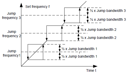
P08.09 | Jump frequency 1 | When the set frequency is in the range of jumping frequency, the VFD will run at the edge of the jumping frequency. The VFD can avoid the mechanical resonance point by setting the jumping frequency. The VFD can set three jumping frequency. But this function will be invalid if all jumping points are 0.
Setting range: 0.00Hz–P00.03 (Max. output frequency) | 0.00Hz | ○ |
P08.10 | Jump frequency bandwidth 1 | 0.00Hz | ○ | |
P08.11 | Jump frequency 2 | 0.00Hz | ○ | |
P08.12 | Jump frequency bandwidth 2 | 0.00Hz | ○ | |
P08.13 | Jump frequency 3 | 0.00Hz | ○ | |
P08.14 | Jumping frequency range 3 | 0.00Hz | ○ | |
P08.15 | Traverse range | This function applies to the industries where traverse and convolution function are required such as textile and chemical fiber. The traverse function means that the output frequency of the VFD is fluctuated with the set frequency as its center. The route of the running frequency is illustrated as below, of which the traverse is set by P08.15 and when P08.15 is set as 0, the traverse is 0 with no function.
Traverse range: The traverse running is limited by upper and low frequency. The traverse range corresponds to the center frequency: traverse range AW=center frequency×traverse range P08.15. Sudden jumping frequency=traverse range AW×sudden jumping frequency range P08.16. When run at the traverse frequency, the value corresponds to the sudden jumping frequency. The raising time of the traverse frequency: The time from the lowest point to the highest one. The declining time of the traverse frequency: The time from the highest point to the lowest one. Setting range of P08.15: 0.0–100.0% (corresponding to the set frequency) Setting range of P08.16: 0.0–50.0% (corresponding to the traverse range) Setting range of P08.17: 0.1–3600.0s Setting range of P08.18: 0.1–3600.0s | 0.0% | ○ |
P08.16 | Sudden jumping frequency range | 0.0% | ○ | |
P08.17 | Traverse boost time | 5.0s | ○ | |
P08.18 | Traverse declining time | 5.0s | ○ | |
P08.19 | Set length | The function codes of setting length, actual length and unit pulse are mainly used to control the fixed length. The length is counted by the pulse signal of HDI terminals input and the HDI terminals are needed to set as the length counting input. Actual length=the length counting input pulse /unit pulse When the actual length P08.20 exceeds the set length P08.19, the multi-function digital output terminals will output ON. Setting range of P08.19: 0–65535m Setting range of P08.20: 0–65535m Setting range of P08.21: 1–10000 Setting range of P08.22: 0.01–100.00cm Setting range of P08.23: 0.001–10.000 Setting range of P08.24: 0.001–1.000 | 0m | ○ |
P08.20 | Actual length | 0m | ● | |
P08.21 | Pulse per rotation | 1 | ○ | |
P08.22 | Alxe perimeter | 10.00 cm | ○ | |
P08.23 | Length ratio | 1.000 | ○ | |
P08.24 | Length correcting coefficient | 1.000 | ○ | |
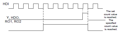
P08.25 | Set count value | The counter works based on the input pulse signals of the HDI terminals. When the count value reaches the specified number, the multi-function output terminal sends the signal of "The speficied count value is reached" and the counter continues to count; when the count value reaches the set number, the multi-function output terminal sends the signal of "The set count value is reached", and the counter will be reset to zero and recount when the next pulse occurs. The value of P08.26 cannot be greater than that of P08.25. The function is illustrated as below:
Setting range of P08.25: P08.26–65535 Setting range of P08.26: 0–P08.25 | 0 | ○ |
P08.26 | Specified count value | 0 | ○ | |
P08.27 | Set running time | Pre-set running time of the VFD. When the accumulative running time achieves the set time, the multi-function digital output terminals will output the signal of "running time arrival". Setting range: 0–65535m | 0m | ○ |
P08.28 | Automatic fault reset times | Automatic fault reset times: set the automatic fault reset times. If the reset time exceeds this set value, the VFD will stop to wait maintenance. Interval time of automatic fault reset: the interval between the time when the fault occurs and the time when the reset action occurs. Setting range of P08.28: 0–10 Setting range of P08.29: 0.1–3600.0s | 0 | ○ |
P08.29 | Interval time of automatic fault reset | 1.0s | ○ | |
P08.30 | Frequency decreasing ratio of the dropping control | The output frequency of the VFD changes as the load. And it is mainly used to balance the power when several VFDs drive one load. Setting range: 0.00–50.00Hz | 0.00Hz | ○ |
P08.31 | Motor shifting | Goodrive300 supports the shift between two motors. This function is used to select the shifting channel. LED ones: shifting channel 0: terminal shifting; digital terminal is 35 1: Modbus communication shifting 2: PROFIBUS/CANopen communication shifting 3: Ethernet communication shifting 4: Reserved LED tens: shifting enabling in operation 0: Disabled 1: Enabled 0x00–0x14 | 0 | ◎ |
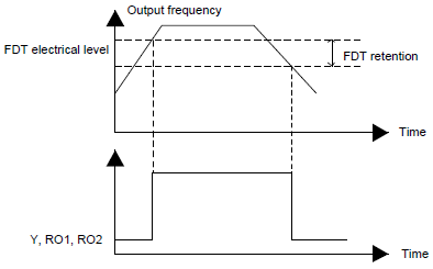
P08.32 | FDT1 electrical level detection value | When the output frequency exceeds the corresponding frequency of FDT electrical level, the multi-function digital output terminals will output the signal of "frequency level detect FDT" until the output frequency decreases to a value lower than (FDT electrical level—FDT retention detection value) the corresponding frequency, the signal is invalid. Below is the ware form diagram:
Setting range of P08.32: 0.00Hz–P00.03 (Max. frequency) Setting range of P08.33: 0.0–100.0% (FDT1 electrical level) Setting range of P08.34: 0.00Hz–P00.03 (Max. frequency) Setting range of P08.35: 0.0–100.0% (FDT2 electrical level) | 50.00 Hz | ○ |
P08.33 | FDT1 retention detection value | 5.0% | ○ | |
P08.34 | FDT2 electrical level detection value | 50.00 Hz | ○ | |
P08.35 | FDT2 retention detection value | 5.0% | ○ | |
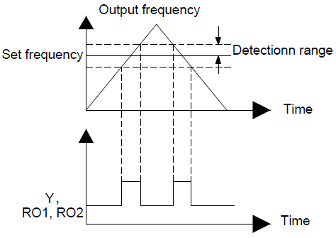
P08.36 | Frequency arrival detection range | When the output frequency is among the positive or negative detection range of the set frequency, the multi-function digital output terminal will output the signal of "frequency arrival", see the diagram below for detailed information:
Setting range: 0.00Hz–P00.03 (Max. frequency) | 0.00Hz | ○ |
P08.37 | Enable dynamic braking | This parameter is used to control the enabling of the internal braking pipe inside the VFD. 0: Disable 1: Enable Note: This function is only applicable to the internal braking pipe. | 0 | ○ |
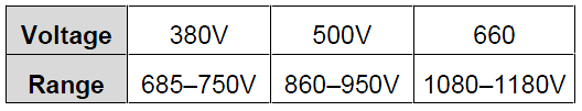
P08.38 | Dynamic braking threshold voltage | Set the initial bus voltage for dynamic braking. This value can be adjusted to perform valid braking on a load. The factory setting changes with the voltage class. Setting range: 200.0–2000.0V To prevent customers from setting a value that is too large, the following setting ranges are recommended:
| 380V voltage: 700.0V | ○ |
500V voltage: 900.0V | ||||
660V voltage: 1120.0V | ||||
P08.39 | Cooling fan running mode | 0: Normal mode 1: The fan keeps running after being powered on. | 0 | ○ |
P08.40 | PWM selection | 0x00–0x21 LED ones: PWM mode selection 0: PWM mode 1, three-phase modulation and two-modulation 1: PWM mode 2, three-phase modulation LED tens: low-speed carrier frequency limit mode 0: Low-speed carrier frequency limit mode 1, the carrier frequency will limit to 2k if it exceeds 2k at low speed 1: Low-speed carrier frequency limit mode 2, the carrier frequency will limit to 4k if it exceeds 4k at low speed 2: No limit | 01 |
◎ |
P08.41 | Overmodulation | LED ones 0: Invalid 1: Valid LED tens (for factory commissioning) 0: Light overcommission; in zone 1 1: Heavy overcommission; in zone 2 | 01 |
◎ |
P08.42 | Keypad data control | 0x000–0x1223 LED ones:frequency enable selection 0: Both ∧/∨ keys and digital potentiometer adjustments are valid 1: Only ∧/∨ keys adjustment is valid 2: Only digital potentiometer adjustments is valid 3: Neither ∧/∨ keys nor digital potentiometer adjustments are valid LED tens: frequency control selection 0: Only valid when P00.06=0 or P00.07=0 1: Valid for all frequency setting manner 2: Invalid for multi-step speed when multi-step speed has the priority LED hundreds: action selection during stopping 0: Setting is valid 1: Valid during running, cleared after stopping 2: Valid during running, cleared after receiving the stop command LED thousands: ∧/∨ keys and digital potentiometer integral function 0: The integral function is valid 1: The integral function is invalid | 0x0000 | ○ |
P08.43 | Integral ratio of the keypad potentiometer | 0.01–10.00s | 0.10s | ○ |
P08.44 | UP/DOWN terminals control | 0x000–0x221 LED ones: frequency control selection 0: UP/DOWN terminals setting valid 1: UP/DOWN terminals setting valid LED tens: frequency control selection 0: Only valid when P00.06=0 or P00.07=0 1: All frequency means are valid 2: When the multi-step are priority, it is invalid to the multi-step LED hundreds: action selection when stop 0: Setting valid 1: Valid in the running, clear after stop 2: Valid in the running, clear after receiving the stop commands | 0x000 | ○ |
P08.45 | UP terminals frequency changing ratio | 0.01–50.00Hz/s | 0.50 Hz/s | ○ |
P08.46 | DOWN terminals frequency changing ratio | 0.01–50.00 Hz/s | 0.50 Hz/s | ○ |
P08.47 | Frequency setting at power loss | 0x000–0x111 LED ones: Action selection when power off. 0: Save when power off 1: Clear when power off LED tens: Action selection when Modbus set frequency off 0: Save when power off 1: Clear when power off LED hundreds: The action selection when other frequency set frequency off 0: Save when power off 1: Clear when power off | 0x000 | ○ |
P08.48 | High bit of initial power consumption | This parameter is used to set the original value of the power comsumotion. The original value of the power comsumotion =P08.48×1000+P08.49 (kWh) Setting range of P08.48: 0–59999 kWh (k) Setting range of P08.49: 0.0–999.9 kWh | 0 kWh | ○ |
P08.49 | Low bit of initial power consumption | 0.0 kWh | ○ | |
P08.50 | Magnetic flux braking | This function code is used to enable magnetic flux. 0: Invalid. 100–150: The bigger the coefficient, the stronger the braking is. This VFD is used to increase the magnetic flux to decelerate the motor. The energy generated by the motor during braking can be converter into heat energy by increasing the magnetic flux. The VFD monitors the state of the motor continuously even during the magnetic flux period. So the magnetic flux can be used in the motor stop, as well as to change the rotation speed of the motor. Its other advantages are: Brake immediately after the stop command. It does not need to wait the magnetic flux weaken. Better cooling for motors. The current of the stator other than the rotor increases during magnetic flux braking, while the cooling of the stator is more effective than the rotor. | 0 | ● |
P08.51 | Current adjustment coefficient on the input side | This function code is used to adjust the displayed current of the AC input side. Setting range: 0.00–1.00 | 0.56 | ○ |