Function code | Name | Detailed instruction of parameters | Default value | Modify |
P09.00 | PID reference source | When the frequency command selection (P00.06, P00. 07) is 7 or the voltage setting channel selection (P04.27) is 6, the running mode of the VFD is procedure PID controlled. The parameter determines the target given channel during the PID procures. 0: Keypad (P09.01) 1: AI1 2: AI2 3: AI3 4: HDI 5: Multi-step speed set 6: Modbus communication set 7: PROFIBUS/CANopen communication set 8: Ethernet communication set 9: Reserved The setting target of procedure PID is a relative one, 100% of the setting equals to 100% of the response of the controlled system. The system is calculated according to the relative value (0–100.0%). Note: Set multi-step speed, which can be compeleted by setting P10 group parameters. For PROFIBUS, Ethernet, and CANopen communication setting, corresponding extension cards are needed. | 0 | ○ |
P09.01 | Keypad PID preset | When P09.00=0, set the parameter whose basic value is the response value of the system. Setting range: -100.0%–100.0% | 0.0% | ○ |
P09.02 | PID feedback source | Select the PID channel by the parameter. 0: AI1 1: AI2 2: AI3 3: HDI 4: Modbus communication feedback 5: PROFIBUS/CANopen communication feedback 6: Ethernet communication feedback 7: Reserved Note: The reference and feedback channel cannot coincide, otherwise, PID cannot control effectively. | 0 | ○ |
P09.03 | PID output feature | 0: PID output is positive: when the feedback signal exceeds the PID given value, the output frequency of the VFD will decrease to balance the PID. For example, the strain PID control during wrapup 1: PID output is negative: When the feedback signal is stronger than the PID given value, the output frequency of the VFD will increase to balance the PID. For example, the strain PID control during wrapdown | 0 | ○ |
P09.04 | Proportional gain (Kp) | The function is applied to the proportional gain P of PID input. P determines the strength of the whole PID adjuster. The parameter of 100 means that when the offset of PID feedback and given value is 100%, the adjusting range of PID adjustor is the Max. frequency (ignoring integral and differential function). Setting range: 0.00–100.00 | 1.00 | ○ |
P09.05 | Intergal time (Ti) | This parameter determines the speed of PID adjustor to carry out integral adjustment on the deviation of PID feedback and reference. When the deviation of PID feedback and reference is 100%, the integral adjustor works continuously after the time (ignoring the proportional effect and differential effect) to achieve the Max. Frequency (P00.03) or the Max. Voltage (P04.31). Shorter the integral time, stronger is the adjustment Setting range: 0.00–10.00s | 0.10s | ○ |
P09.06 | Differential time (Td) | This parameter determines the strength of th e change ratio when PID adjustor carries out integral adjustment on the deviation of PID feedback and reference. If the PID feedback changes 100% during the time, the adjustment of integral adjustor (ignoring the proportional effect and differential effect) is the Max. Frequency (P00.03) or the Max. Voltage (P04.31). Longer the integral time, stronger is the adjusting. Setting range: 0.00–10.00s | 0.00s | ○ |
P09.07 | Sampling cycle (T) | This parameter means the sampling cycle of the feedback. The adjustor operates each sampling cycle. The longer the sapling cycle is, the slower the response is. Setting range: 0.000–10.000s | 0.100s | ○ |
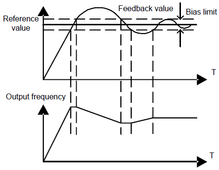
P09.08 | PID control deviation limit | The output of PID system is the maximum deviation corresponding to close loop reference. As shown in the diagram below, PID adjustor stops to work during the deviation limit. Set the function properly to adjust the accuracy and stability of the system.
Setting range: 0.0–100.0% | 0.0% | ○ |
P09.09 | Output upper limit of PID | This parameter is used to set the upper and lower limit of the PID adjustor output. 100.0 % corresponds to max. frequency or the max. voltage of ( P04.31) Setting range of P09.09: P09.10–100.0% Setting range of P09.10: -100.0%–P09.09 | 100.0% | ○ |
P09.10 | Output lower limit of PID | 0.0% | ○ | |
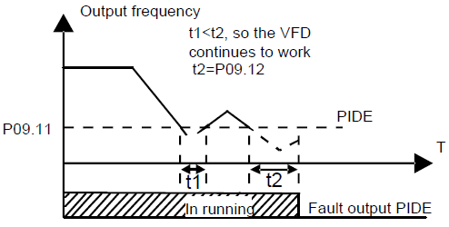
P09.11 | Detection value of feedback offline | Set the detection value of feedback offline, when the feedback detection value is smaller than or equals to the detected value, and the lasting time exceeds the set value in P09.12, the VFD will report "PID feedback offline fault" and the keypad will display PIDE.
Setting range of P09.11: 0.0–100.0% Setting range of P09.12: 0.0–3600.0s | 0.0% | ○ |
P09.12 | Detection time of feedback offline | 1.0s | ○ | |
P09.13 | PID adjustment | 0x0000–0x1111 LED ones: 0: Keep on integral adjustment when the frequency achieves the upper and low limit; the integration shows the change between the reference and the feedback unless it reaches the internal integral limit. When the trend between the reference and the feedback changes, it needs more time to offset the impact of continuous working and the integration will change with the trend. 1: Stop integral adjustment when the frequency achieves the upper and low limit. If the integration keeps stable, and the trend between the reference and the feedback changes, the integration will change with the trend quickly. LED tens: P00.08 is 0 0: The same with the setting direction; if the output of PID adjustment is different from the current running direction, the internal will output 0 forcedly. 1: Opposite to the setting direction LED hundreds: P00.08 is 0 0: Limit to the maximum frequency 1: Limit to frequency A LED thousands: 0: A+B frequency, the buffer of A frequency is invalid 1: A+B frequency, the buffer of A frequency is valid ACC/DEC is determined by ACC time 4 of P08.04 | 0x0001 | ○ |
P09.14 | Proportional gain at low frequency (Kp) | 0.00–100.00 | 1.00 | ○ |
P09.15 | PID command of ACC/DEC time | 0.0–1000.0s | 0.0s | ○ |
P09.16 | PID output filter time | 0.000–10.000s | 0.000s | ○ |