Function code | Name | Detailed instruction of parameters | Default value | Modify |
P11.00 | Phase loss protection | 0x00–0x11 LED ones: 0: Input phase loss protection disable 1: Input phase loss protection enable LED tens: 0: Output phase loss protection disable 1: Output phase loss protection enable | 11 | ○ |
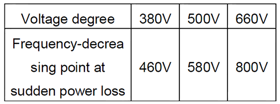
P11.01 | Frequency-decreasing at sudden power loss | 0: Disable 1: Enable | 0 | ○ |
P11.02 | Frequency decreasing ratio at sudden power loss | Setting range: 0.00Hz/s–P00.03 (Max. frequency) After the power loss of the grid, the bus voltage drops to the sudden frequency-decreasing point, the VFD begin to decrease the running frequency at P11.02, to make the VFD generate power again. The returning power can maintain the bus voltage to ensure a rated running of the VFD until the recovery of power.
Note: 1. Adjust the parameter properly to avoid the stopping caused by VFD protection during the switching of the grid. 2. Disable input phase loss protection to enable this function. | 10.00 Hz/s | ○ |
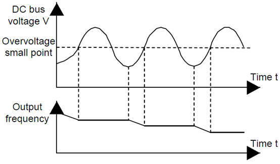
P11.03 | Overvoltage stall protection | 0:Disable 1: Enable
| 1 | ○ |
P11.04 | Voltage protection of overvoltage stall | 120–150%(standard bus voltage)( 380V) | 136% | ○ |
120–150%(standard bus voltage)( 500V) | 132% | |||
120–150%(standard bus voltage)(660V) | 120% | |||
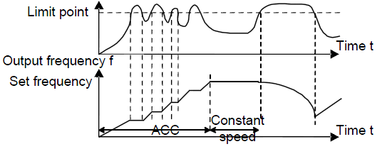
P11.05 | Current limit action selection | The actual increasing ratio of motor speed is lower than the ratio of output frequency because of the big load during ACC running. It is necessary to take measures to avoid overcurrent fault and the VFD trips. Ones: current limit: 0: Invalid 1: Valid Tens: overload alarm of hardware current limit (for factory commissioning) 0: Valid 1: Invalid | 01 | ◎ |
P11.06 | Automatic current limit | During the running of the VFD, it will detect the output current and compare it with the limit level defined in P11.06. If it exceeds the level, the VFD will run at stable frequency in ACC running, or the VFD will derate to run during the constant running. If it exceeds the level continuously, the output frequency will keep on decreasing to the lower limit. If the output current is detected to be lower than the limit level, the VFD will accelerate to run.
Setting range of P11.06: 50.0–200.0% Setting range of P11.07: 0.00–50.00Hz/s | 160.0% | ◎ |
P11.07 | Frequency-decreasing ratio during current limit | 10.00 Hz/s | ◎ | |
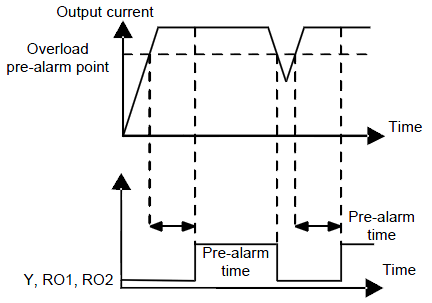
P11.08 | Overload pre-alarm of motor/VFD | The output current of the VFD or the motor is above P11.09 and the lasting time is beyond P11.10, overload pre-alarm will be output.
Setting range of P11.08: Enable and define the overload pre-alarm of the VFD or the motor. Setting range: 0x000–0x131 LED ones: 0: Overload pre-alarm of the motor, corresponding to the rated current of the motor 1: Overload pre-alarm of the VFD, corresponding to the rated current of the VFD LED tens: 0: The VFD continues to work after underload pre-alarm 1: The VFD continues to work after underload pre-alarm and the VFD stops to run after overload fault 2: The VFD continues to work after overload pre-alarm and the VFD stops to run after underload fault LED hundreds : 0: Detection all the time 1: Detection in constant running Setting range of P11.09: P11.11–200% Setting range of P11.10: 0.1–3600.0s | 0x000 | ○ |
P11.09 | Overload pre-alarm detection | 150% | ○ | |
P11.10 | Overload pre-alarm detection time | 1.0s | ○ | |
P11.11 | Underload pre-alarm detection | If the VFD current or the output current is lower than P11.11, and its lasting time is beyond P11.12, the VFD will output underload pre-alarm. Setting range of P11.11: 0–P11.09 Setting range of P11.12: 0.1–3600.0s | 50% | ○ |
P11.12 | Underload pre-alarm detection time | 1.0s | ○ | |
P11.13 | Output terminal action during fault | Select the action of fault output terminals on undervoltage and fault reset. 0x00–0x11 LED ones: 0: Action under fault undervoltage 1: No action under fault undervoltage LED tens: 0: Action during the automatic reset 1: No action during the automatic reset | 0x00 | ○ |
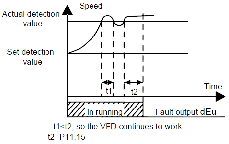
P11.14 | Speed deviation detection | 0.0–50.0% Set the speed deviation detection time. | 10.0% | ○ |
P11.15 | Speed deviation detection time | This parameter is used to see the speed deviation detection time.
Setting range of P11.15: 0.0–10.0s | 0.5s | ○ |
P11.16 | Automatic frequency-decreasing at voltage drop | 0: Invalid 1: Valid; ensure rated output torque when voltge drop | 0 | ○ |