Function code | Name | Detailed instruction of parameters | Default value | Modify | |
P12.00 | Motor type 2 | 0: Asynchronous motor 1: Synchronous motor Note: Switch the current motor by the switching channel of P08.31. | 0 | ◎ | |
P12.01 | Rated power of asynchronous motor 2 | 0.1–3000.0kW | Set the parameter of the controlled asynchronous motor. In order to ensure the controlling performance, set the P12.01–P12.05 according to the name plate of the asynchronous motor. Goodrive300 series VFDs provide the function of parameter autotuning. Correct parameter autotuning comes from the correct setting of the motor name plate. In order to ensure the controlling performance, please configure the motor according to the standard principles, if the gap between the motor and the standard one is huge, the features of the VFD will decrease. Note: Reset the rated power of the motor (P12.01), initialize the motor parameter of P12.02–P12.05 | Depend on model | ◎ |
P12.02 | Rated frequency of asynchronous motor 2 | 0.01Hz–P00.03 (Max. frequency) | 50.00 Hz | ◎ | |
P12.03 | Rated speed of asynchronous motor 2 | 1–36000rpm | Depend on model | ◎ | |
P12.04 | Rated voltage of asynchronous motor 2 | 0–1200V | Depend on model | ◎ | |
P12.05 | Rated current of asynchronous motor 2 | 0.8–6000.0A | Depend on model | ◎ | |
P12.06 | Stator resistor of asynchronous motor 2 | 0.001–65.535Ω | After finish the motor parameter autotuning, the set value of P12.06–P12.10 will renew automatically. These parameters are basic parameters controlled by vectors which directly impact the features. Note: Users cannot modify the parameters freely. | Depend on model | ○ |
P12.07 | Rotor resistor of asynchronous motor 2 | 0.001–65.535Ω | Depend on model | ○ | |
P12.08 | Leakage inductance of asynchronous motor 2 | 0.1–655.35mH | Depend on model | ○ | |
P12.09 | Mutual inductance of asynchronous motor 2 | 0.1–655.35mH | Depend on model | ○ | |
P12.10 | Non-load current of asynchronous motor 2 | 0.1–6553.5A | Depend on model | ○ | |
P12.11 | Magnetic saturation coefficient 1 for the iron core of AM2 | 0.0–100.0% | 80.0% | ◎ | |
P12.12 | Magnetic saturation coefficient 2 for the iron core of AM2 | 0.0–100.0% | 68.0% | ◎ | |
P12.13 | Magnetic saturation coefficient 3 for the iron core of AM2 | 0.0–100.0% | 57.0% | ◎ | |
P12.14 | Magnetic saturation coefficient 4 for the iron core of AM2 | 0.0–100.0% | 40.0% | ◎ | |
P12.15 | Rated power of synchronous motor 2 | 0.1–3000.0kW | Set the parameter of the controlled asynchronous motor. In order to ensure the controlling performance, set the P12.151–P12.19 according to the name plate of the asynchronous motor. Goodrive300 series VFDs provide the function of parameter autotuning. Correct parameter autotuning comes from the correct setting of the motor name plate. In order to ensure the controlling performance, please configure the motor according to the standard principles, if the gap between the motor and the standard one is huge, the features of the VFD will decrease. Note: Reset the rated power of the motor(P12.15),initialize the motor parameter of P12.16– P12.19. | Depend on model | ◎ |
P12.16 | Rated frequency of synchronous motor 2 | 0.01Hz–P00.03 (Max. frequency) | 50.00 Hz | ◎ | |
P12.17 | Number of poles pairs for synchronous motor 2 | 1–50 | 2 | ◎ | |
P12.18 | Rated voltage of synchronous motor 2 | 0–1200V | Depend on model | ◎ | |
P12.19 | Rated current of synchronous motor 2 | 0.8–6000.0A | Depend on model | ◎ | |
P12.20 | Stator resistor of synchronous motor 2 | 0.001–65.535Ω | Depend on model | ○ | |
P12.21 | Direct axis inductance of synchronous motor 2 | 0.01–655.35mH | After finish the motor parameter autotuning, the set value of P12.20–P12.22 will renew automatically. These parameters are basic parameters controlled by vectors which directly impact the features. When P00.15=1, the set value of P12.23 can be updated through autotuning automatically, and there is no need to change the value of P12.23; when P00.15=2, the set value of P12.23 cannot be updated through autotuning, please account and update the value of P12.23. Note:Users cannot modify the parameters freely. | Depend on model | ○ |
P12.22 | Quadrature axis inductance of synchronous motor 2 | 0.01–655.35mH | Depend on model | ○ | |
P12.23 | Back EMF constant of synchronous motor 2 | When P00.15=2, the set value of P12.23 cannot be updated by autotuning, please count according to the following method. The counter-electromotive force constant can be counted according to the parameters on the name plate of the motor. There are three ways to count: 1. If the name plate designate the counter-electromotive force constant Ke, then: E=(Ke×nN×2π)/ 60 2. If the name plate designate the counter-electromotive force constant E’(V/1000r/min), then: E=E’×nN/1000 3. Iif the name plate does not designate the above parameters, then: E=P/√3×I In the above formulas: nN is the rated rotation speed, P is the rated power and I is the rated current. Setting range: 0–10000 | 300 | ○ | |
P12.24 | Initial pole position of synchronous motor 2 (reserved) | 0–FFFFH (reserved) | 0x0000 | ● | |
P12.25 | Identification current of synchronous motor 2 (reserved) | 0%–50%(the rated current of the motor) (reserved) | 10% | ● | |
P12.26 | Motor 2 overload protection | 0: No protection 1: Common motor(with low speed compensation) 2: Variable frequency motor (without low speed compensation) | 2 | ◎ | |
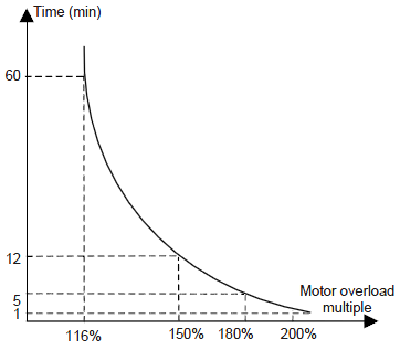
P12.27 | Motor 2 overload protection coefficient | Times of motor overload M = Iout/(In×K) In is the rated current of the motor, Iout is the output current of the VFD and K is the motor protection coefficient. The smaller K is, the greater M is, and the more likely protection is implemented. When M=116%, protection is performed after motor overload lasts for 1 hour; when M=150%, protection is performed after motor overload lasts for 12 minutes; when M=180%, protection is performed after motor overload lasts for 5 minutes; when M=200%, protection is performed after motor overload lasts for 60 seconds; and when M≥ 400%, protection is performed immediately.
Setting range: 20.0%–120.0% | 100.0% | ○ | |
P12.28 | Correction coefficient of motor 2 power | Correct the power displaying of motor 2. Only impact the displaying value other than the control performance of the VFD. Setting range: 0.00–3.00 | 1.00 | ○ | |
P12.29 | Parameter display of motor 2 | 0: Display according to the motor type: only the parameters corresponding to the current motor type are displayed for the convenient for the customers in this mode. 1: All parameters are displayed: all parameters are displayed in this mode. | 0 | ○ | |