You can perform various operations on the VFD by using the keypad, including entering/exiting menus, parameter selection, list modification and parameter addition.
5.4.1 Enter/exit menu
Regarding the monitoring menu, the operation relation between enter and exit is shown below.
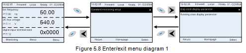
Regarding the system menu, the operation relation between enter and exit is shown below.
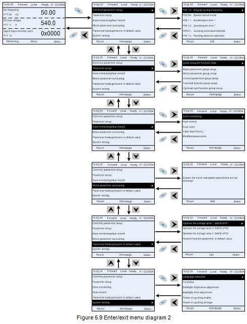
The keypad menu setup is shown in the following.
Level 1 | Level 2 | Level 3 | Level 4 |
Common parameter setup | / | / | P00.10: Set frequency via keypad |
P00.00: Speed control mode | |||
Pxx.xx : Common parameter setup xx | |||
Quick setup for function code | / | Pxx.xx | |
Parameter setup | Basic parameter group setup | P00: Basic function group | P00.xx |
P07: HMI group | P07.xx | ||
P08: Enhance function group | P08.xx | ||
P11: Protection parameter group | P11.xx | ||
P14: Serial communication function group | P14.xx | ||
P99: Factory function group | P99.xx | ||
Motor parameter group setup | P02.xx | ||
P12: Motor 2 parameter group | P12.xx | ||
P20: Motor 1 encoder group | P20.xx | ||
P24: Motor 2 encoder group | P24.xx | ||
Control parameter group setup | P01.xx | ||
P03.xx | |||
P04.xx | |||
P09: PID control group | P09.xx | ||
P10: Simple PLC and multi-step speed control group | P10.xx | ||
P13: Synchronous motor control parameter group | P13.xx | ||
P21: Position control group | P21.xx | ||
P22: Spindle positioning group | P22.xx | ||
P23: Motor 2 vector control group | P23.xx | ||
Terminal function group setup | P05: Input terminal group | P05.xx | |
P06: Output terminal group | P06.xx | ||
P98: AIAO calibration function group | P98.xx | ||
Optional card function group setup | P15: Communication expansion card 1 function group | P15.xx | |
P16: Communication expansion card 2 function group | P16.xx | ||
P25: Expansion I/O card input function group | P25.xx | ||
P26: Expansion I/O card output function group | P26.xx | ||
P27: PLC function group | P27.xx | ||
P28: Master/slave function group | P28.xx | ||
Default function group setup | P90: Customized function group 1 | P90.xx | |
P91: Customized function group 2 | P91.xx | ||
P92: Customized function group 3 | P92.xx | ||
P93: Customized function group 4 | P93.xx | ||
State monitoring/fault record | State monitoring | P07: HMI group | P07.xx |
P17: State-check function group | P17.xx | ||
P18: Closed-loop vector state check function group | P18.xx | ||
P19: Expansion card state check function group | P19.xx | ||
Fault record | / | P07.27: Type of present fault | |
P07.28: Type of the last fault | |||
P07.29: Type of the last but one fault | |||
P07.30: Type of the last but two fault | |||
P07.31: Type of the last but three fault | |||
P07.32: Type of the last but four fault | |||
Fault state | / | P07.33: Running frequency of present fault | |
P07.34: Ramps frequency of present fault | |||
P07.xx: xx state of the last but xx fault | |||
Clear fault history | / | Sure to clear fault history? | |
Modified parameter | / | Pxx.xx has modified parameter 1 | |
Pxx.xx has modified parameter 2 | |||
Pxx.xx has modified parameter xx | |||
Motor parameter autotuning | / | / | Complete parameter rotary autotuning |
Complete parameter static autotuning | |||
Partial parameter static autotuning | |||
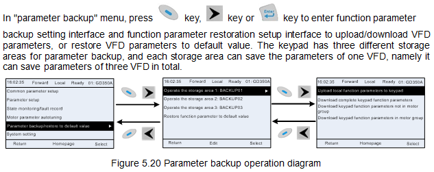
Parameter backup/restore default value | / | Operate the storage area 1: BACKUP01 | Upload local function parameter to keypad |
Download complete keypad function parameter | |||
Download key function parameters which are not in motor group | |||
Download keypad function parameters which are in motor group | |||
Operate the storage area 2: BACKUP012 | |||
Operate the storage area 3: BACKUP03 | |||
Restore function parameter to default value | Ensure to restore function parameters to default value? | ||
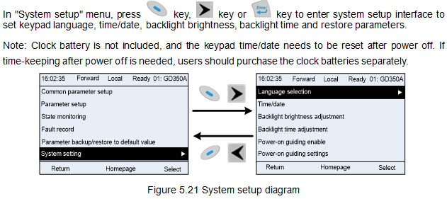
System setup | / | / | Language selection |
Time/date | |||
Backlight brightness regulation | |||
Backlight time adjustment | |||
Power-on guiding enable | |||
Power-on guiding settings | |||
Keyboard burning selection | |||
Fault time enable | |||
Control board burning selection |
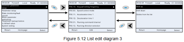
5.4.2 List edit
The monitoring items displayed in the parameter list of stop state can be added by users as needed (through the menu of the function code in state check group), and the list can also be edited by users e.g. "shift up", "shift down" and "delete from the list". The edit function is shown in the interface below.
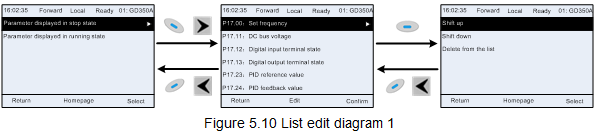
Press  key to enter edit interface, select the operation needed, and press
  key,
key,  key or
  key to confirm the edit operation and return to the previous menu (parameter list), the returned list is the list edited. If
  key or
  key is pressed in edit interface wihouth selecting
edit operation, it will return to the previous menu (parameter list remain unchanged).
Note: For the parameter objects in the list header, shift-up operation will be invalid, and the same principle can be applied to the parameter objects in the list footer; after deleting a certain parameter, the parameter objects under it will be shifted up automatically.
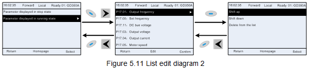
The monitoring items displayed in the parameter list of running state can be added by users as needed (through the menu of the function code in state check group), and the list can also be edited by users e.g. "shift up", "shift down" and "delete from the list". The edit function is shown in the interface below.
The parameter list of common parameter setup can be added, deleted or adjusted by users as needed, including delete, shift-up and shift-down; the addition function can be set in a certain function code of a function group. The edit function is shown in the figure below.
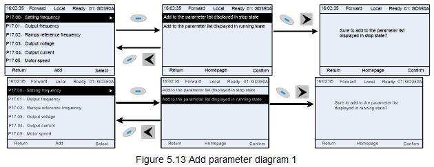
5.4.3 Add parameters to the parameter list displayed in stop/running state
In the fourth-level menu of "State monitoring", the parameters in the list can be added to the "parameter displayed in stop state" list or "parameter displayed in running state" list as shown below.
Press  key to enter parameter addition interface, select the operation needed, and press
  key,
key,  key or
  key to confirm the addition operation. If this parameter is not included in
the "parameter displayed in stop state" list or "parameter displayed in running state" list, the parameter added will be at the end of the list; if the parameter is already in the "parameter displayed in stop state" list or "parameter displayed in running state" list, the addition operation will be invalid. If
 key or
  key is pressed without selecting addition peration in "Addition" interface, it will
return to monitoring parameter list menu.
Part of the monitoring parameters in P07 HMI group can be added to the "parameter displayed in stop state" list or "parameter displayed in running state" list; All the parameters in P17, P18 and P19 group can be added to the "parameter displayed in stop state" list or "parameter displayed in running state" list.
Up to 16 monitoring parameters can be added to the "parameter displayed in stop state" list; and up to 32 monitoring parameters can be added to the "parameter displayed in running state" list.
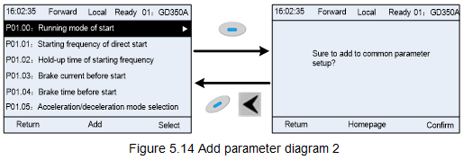
5.4.4 Add parameter to common parameter setup list
In fourth-level menu of "parameter setup" menu, the parameter in the list can be added to the "common parameter setup" list as shown below.
Add  key to enter addition interface, and press
  key,
key,  key or
  key to confirm the addition operation. If this parameter is not included in the original "common parameter setup" list, the newly-added parameter will be at the end of the list; if this parameter is already in the "common parameter setup" list, the addition operation will be invalid. If
  key or
  key is pressed without selecting addition operation, it will return to parameter setup list menu.
All the function code groups under parameter setup sub-menu can be added to "common parameter setup" list. Up to 64 function codes can be added to the "common parameter setup" list.
5.4.5 Parameter selection edit interface
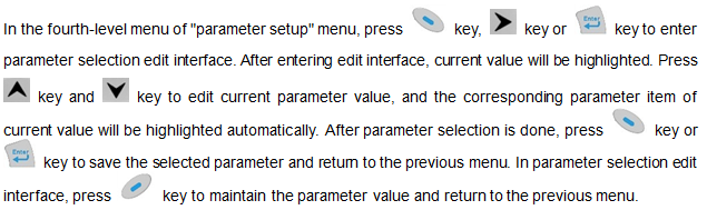
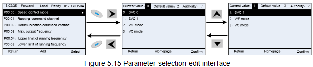
In parameter selection edit interface, the "authority" on the top right indicates whether this parameter is editable or not.
"√" indicates the set value of this parameter can be modified under current state.
"×" indicates the set value of this parameter cannot be modified under current state.
"Current value" indicates the value of current option.
"Default value" indicates the default value of this parameter.
5.4.6 Parameter setup edit interface
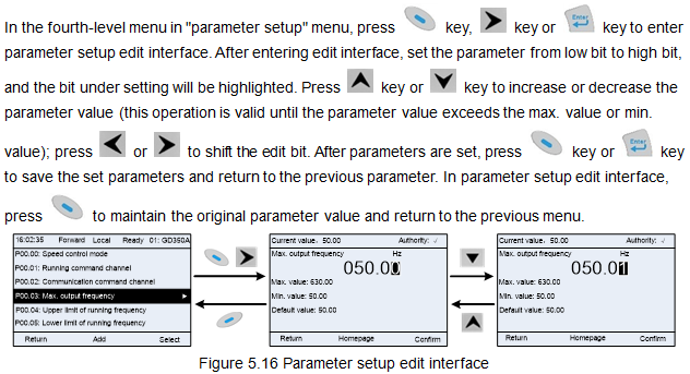
In parameter selection edit interface, the "authority" on the top right indicates whether this parameter can be modified or not.
"√" indicates the set value of this parameter can be modified under current state.
"×" indicates the set value of this parameter cannot be modified under current state.
"Current value" indicates the value saved last time.
"Default value" indicates the default value of this parameter.
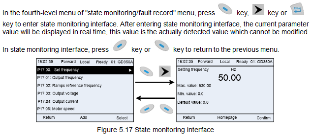
5.4.7 State monitoring interface
5.4.8 Motor parameter autotuning
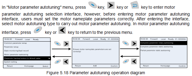
After selecting motor autotuning type, enter motor parameter autotuning interface, and press RUN key to start motor parameter autotuning. After autotuning is done, a prompt will pop out indicating autotuning is succeeded, and then it will return to the main interface of stop. During autotuning, users can press STOP/RST key to terminate autotuning; if any fault occur during autotuning, the keypad will pop out a fault interface.
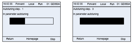
Figure 5.19 Parameter autotuning finished
5.4.9 Parameter backup
5.4.10 System setup
5.4.11 Power-on guiding settings
The keyboard supports the power-on guiding function, mainly for the first power-on situation, guiding the user to enter the setting menu, and gradually implementing basic functions such as basic parameter setting, direction judgment, mode setting and autotuning. The power-on guiding enable menu guides the user to enable power-on to boot each time. Power-on guiding setup menu guides the user to set step by step according to the functions.
The power-on guide is shown as below.
Level 1 | Level 2 | Level 3 | Level 4 | ||||
Language | 0: Simplified Chinese | Power-on guiding enable | 0: Power-on each time | Whether to enter the power-on guiding settings? | 0:Yes | Whether to test the motor rotation direction? | Yes |
1:English | 1: Only once | 1:No | No | ||||
Setting channel of A frequency command | 0: Keypad | Press the JOG button first. It is currently forward, Is it consistent with the expectations? | Yes | ||||
1: AI1 | No | ||||||
2: AI2 | P02.00 Type of motor 1 | 0: AM | |||||
3: AI3 | 1: SM | ||||||
4: High-speed pulse HDIA | P02.01 Rated power of AM 1 | ||||||
5: Simple PLC program | P02.02 Rated frequency of AM 1 | ||||||
6: Multi-step speed running | P02.03 Rated speed of AM 1 | ||||||
7: PID control | P02.04 Rated voltage of AM 1 | ||||||
8: Modbus/ | P02.05 Rated current of AM 1 | ||||||
9: Profibus/CANopen/DeviceNet communication | P02.15 Rated power of SM 1 | ||||||
10: Ethernet communication | P02.16 Rated frequency of SM 1 | ||||||
11: High-speed pulse HDIB | P02.17 Number of pole pairs of SM 1 | ||||||
12: Pulse train AB | P02.18 Rated voltage of SM 1 | ||||||
13: EtherCat/Profinet/EtherNetIP communication | P02.19 Rated current of SM 1 | ||||||
14: PLC card | Whether to conduct autotuning? | Yes | |||||
15: Reserved | No | ||||||
Running command channel | 0: Keypad | Motor parameter autotuning interface | |||||
1: Terminal | |||||||
2: Communication command | |||||||
Communication running command channel | 0: Modbus/ | ||||||
1: PROFIBUS / CANopen /Devicenet communication | |||||||
2: Ethernet Communication | |||||||
3: EtherCat /Profinet/EtherNetIP communication | |||||||
4: PLC programmable card | |||||||
5: Wireless communication card | |||||||
Enable energy- | 0: Disable | ||||||
1: Enable | |||||||
Speed control mode | 0: Sensorless vector control (SVC) mode 0 | ||||||
1: Sensorless vector control (SVC) mode 1 | |||||||
2: VF control | |||||||
3: Closed-loop vector control mode | |||||||
Stop mode | 0: Decelerate to stop | ||||||
1: Coast to stop | |||||||
ACC time 1 | |||||||
DEC time 1 | |||||||