5.5.1 What this section contains
This section introduces the function modules inside the VFD.
| ² Ensure all the terminals are fixed and tightened firmly. ² Ensure the motor matches with the VFD power. |

5.5.2 Common commissioning procedure
The common operation procedure is shown in the following (taking motor 1 as an example).
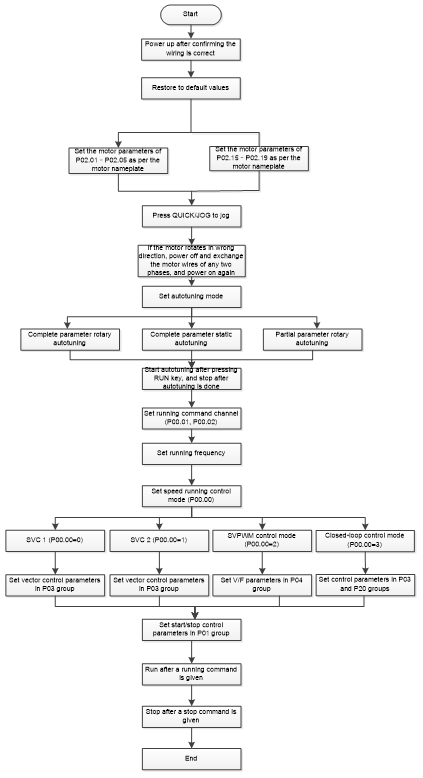
Note: If fault occurred, rule out the fault cause according to "fault tracking".
The running command channel can be set by terminal commands besides P00.01 and P00.02.
Current running command channel P00.01 | Multi-function terminal function (36) Command switches to keypad | Multi-function terminal function (37) Command switches to terminal | Multi-function terminal function (38) Command switches to communication |
Keypad | / | Terminal | Communication |
Terminal | Keypad | / | Communication |
Communication | Keypad | Terminal | / |
Note: "/" means this multi-function terminal is invalid under current reference channel.
Related parameter list:
Function code | Name | Description | Default |
Speed control mode | 0: Sensorless vector control (SVC) mode 0 1: Sensorless vector control (SVC) mode 1 2: Space voltage vector control mode 3: Closed-loop vector control mode Note: To select 0, 1, or 3 as the control mode, enable the VFD to perform motor parameter autotuning first. | 2 | |
Channel of running commands | 0: Keypad 1: Terminal 2: Communication | 0 | |
Communication mode of running commands | 0: Modbus/Modbus TCP 1: Profibus/CANopen/DeviceNet 2: Ethernet 3: EtherCAT/Profinet/EtherNetIP 4: Programmable expansion card 5: Wireless communication card | 0 | |
Motor parameter autotuning | 0: No operation 1: Rotary autotuning. 2: Static autotuning 1 (comprehensive autotuning); static autotuning 1 is used in cases where the motor cannot be disconnected from load. 3: Static autotuning 2 (partial autotuning); when the present motor is motor 1, only P02.06, P02.07 and P02.08 are autotuned; when the present motor is motor 2, only P12.06, P12.07 and P12.08 are autotuned. 4: Rotary autotuning 2, similar to rotary autotuning 1, but valid only to AMs 5: Static autotuning 3 (partial autotuning), valid only to AMs | 0 | |
Function parameter restore | 0: No operation 1: Restore default values 2: Clear fault records Note: After the selected operation is performed, the function code is automatically restored to 0. Restoring the default values may delete the user password. Exercise caution when using this function. | 0 | |
Type of motor 1 | 0: Asynchronous motor (AM) 1: Synchronous motor (SM) | 0 | |
Rated power of AM 1 | 0.1–3000.0kW | Model depended | |
Rated frequency of AM 1 | 0.01Hz–P00.03 (Max. output frequency) | 50.00Hz | |
Rated speed of AM 1 | 1–60000rpm | Model depended | |
Rated voltage of AM 1 | 0–1200V | Model depended | |
Rated current of AM 1 | 0.8–6000.0A | Model depended | |
Rated power of SM 1 | 0.1–3000.0kW | Model depended | |
Rated frequency of SM 1 | 0.01Hz–P00.03 (Max. output frequency) | 50.00Hz | |
Number of pole pairs of SM 1 | 1–50 | 2 | |
Rated voltage of SM 1 | 0–1200V | Model depended | |
Rated current of SM 1 | 0.8–6000.0A | Model depended | |
Function selection of multifunction digital input terminals (S1–S4, HDIA, HDIB) | 36: Switch the running command channel to keypad 37: Switch the running command channel to terminal 38: Switch the running command channel to communication | ||
Reserved | |||
QUICK/JOG key function selection | Range: 0x00–0x27 Ones place: Function of QUICK/JOG 0: No function 1: Jog 2: Reserved 3: Switch between forward and reverse rotating 4: Clear the UP/DOWN setting 5: Coast to stop 6: Switch command channels in sequence 7: Reserved Tens place: Reserved | 0x01 |
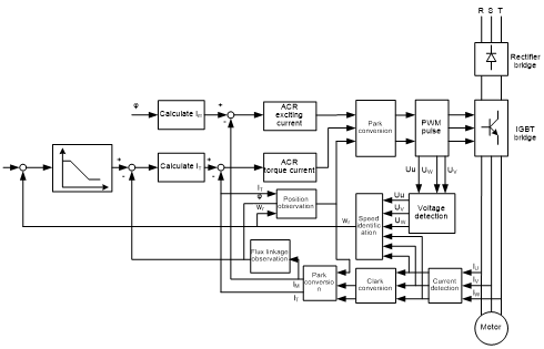
5.5.3 Vector control
AMs feature high order, nonlinearity, strong coupling and multi-variables, which increase difficulty to control AMs during actual application. The vector control technology solves this situation as follows: measures and controls the stator current vector of the AM, and then decomposes the stator current vector into exciting current (current component that generates internal magnet field) and torque current (current component that generates torque) based on field orientation principle, and therefore controls the amplitude values and phase positions of the two components (namely, controls the stator current vector of the AM) to realize decoupled control on exciting current and torque current, thus achieving high-performance speed regulation of the AM.
The VFD uses the sensor-less vector control algorithm, which can be used to drive AMs and permanent-magnet SMs simultaneously. As the core algorithm of vector control is based on accurate motor parameter models, the accuracy of motor parameters affects vector control performance. It is recommended to enter accurate motor parameters and autotune motor parameters before executing vector control.
As the vector control algorithm is complicated, exercise caution before modifying vector control function parameters.
Function code | Name | Description | Default |
Speed control mode | 0: Sensorless vector control (SVC) mode 0 1: Sensorless vector control (SVC) mode 1 2: Space voltage vector control mode 3: Closed-loop vector control mode Note: To select 0, 1, or 3 as the control mode, enable the VFD to perform motor parameter autotuning first. | 2 | |
Motor parameter autotuning | 0: No operation 1: Rotary autotuning 1. Comprehensive motor parameter autotuning. It is recommended to use rotating autotuning when high control accuracy is needed. 2: Static autotuning 1 (comprehensive autotuning); static autotuning 1 is used in cases where the motor cannot be disconnected from load. 3: Static autotuning 2 (partial autotuning); when the present motor is motor 1, only P02.06, P02.07 and P02.08 are autotuned; when the present motor is motor 2, only P12.06, P12.07 and P12.08 are autotuned. 4: Rotary autotuning 2. Similar to rotary autotuning 1, but it is valid only for AMs. 5: Static autotuning 3 (partial autotuning), valid only for AMs. | 0 | |
Type of motor 1 | 0: Asynchronous motor (AM) 1: Synchronous motor (SM) | 0 | |
Speed-loop proportional gain 1 | 0–200.0 | 20.0 | |
Speed-loop integral time 1 | 0.000–10.000s | 0.200s | |
Low-point frequency for switching | 0.00Hz–P03.05 | 5.00Hz | |
Speed-loop proportional gain 2 | 0–200.0 | 20.0 | |
Speed-loop integral time 2 | 0.000–10.000s | 0.200s | |
High-point frequency for switching | 10.00Hz | ||
Speed-loop output filter | 0–8 (0–28/10ms) | 0 | |
Electromotive slip compensation coefficient of vector control | 50%–200% | 100% | |
Braking slip compensation coefficient of vector control | 50%–200% | 100% | |
Current-loop proportional coefficient P | 0–65535 | 1000 | |
Current-loop integral coefficient I | 0–65535 | 1000 | |
Torque setting method | 11: Keypad (P03.12) 2: AI1 (100% corresponding to three times the motor rated current) 3: AI2 (same as the above) 4: AI3 (same as the above) 5: Pulse frequency HDIA (same as the above) 6: Multi-step torque (same as the above) 7: Modbus/Modbus TCP communication (same as the above) 8: Profibus/CANopen/DeviceNet communication (same as the above) 9: Ethernet communication (same as the above) 10: Pulse frequency HDIB (same as the above) 11: EtherCat/Profinet/EtherNetIP communication 12: Programmable expansion card Note: For setting methods 2–12, 100% corresponds to three times the motor rated current. | 1 | |
Torque set through keypad | -300.0%–300.0% (of the motor rated current) | 50.0% | |
Torque reference filter time | 0.000–10.000s | 0.010s | |
Setting source of forward rotation upper-limit frequency in torque control | 0: Keypad (P03.16) 1: AI1 (100% corresponding to the max. frequency) 2: AI2 (same as the above) 3: AI3 (same as the above) 4: Pulse frequency HDIA (same as the above) 5: Multi-step setting (same as the above) 6: Modbus/Modbus TCP communication (same as the above) 7: Profibus/CANopen/DeviceNet communication (same as the above) 8: Ethernet communication (same as the above) 9: Pulse frequency HDIB (same as the above) 10: EtherCat/Profinet/EtherNetIP communication 11: Programmable expansion card 12: Reserved Note: For setting methods 1–11, 100% corresponds to the maximum frequency. | 0 | |
Setting source of reverse rotation upper-limit frequency in torque control | 0: Keypad (set by P03.17) 1–11: Same as those of P03.14 | 0 | |
Forward rotation upper-limit frequency set through keypad in torque control | Setting range: 0.00 Hz–P00.03 (Max. output frequency) | 50.00Hz | |
Reverse rotation upper-limit frequency set through keypad in torque control | 50.00Hz | ||
Setting source of electromotive torque upper limit | 0: Keypad (P03.20) 1: AI1 (100% corresponding to three times the motor rated current) 2: AI2 (same as the above) 3: AI3 (same as the above) 4: Pulse frequency HDIA (same as the above) 5: Modbus/Modbus TCP communication (same as the above) 6: Profibus/CANopen/DeviceNet communication (same as the above) 7: Ethernet communication (same as the above) 8: Pulse frequency HDIB (same as the above) 9: EtherCAT/Profinet communication 10: Programmable expansion card 11: Reserved Note: For setting methods 1–10, 100% corresponds to three times the motor rated current. | 0 | |
Setting source of braking torque upper limit | 0: Keypad (set by P03.21) 1–10: Same as those for P03.18 | 0 | |
Electromotive torque upper limit set through keypad | 0.0–300.0% (of the motor rated current) | 180.0% | |
Braking torque upper limit set through keypad | 180.0% | ||
Weakening coefficient in constant power zone | 0.1–2.0 | 0.3 | |
Lowest weakening point in constant power zone | 10%–100% | 20% | |
Max. voltage limit | 0.0–120.0% | 100.0% | |
Pre-exciting time | 0.000–10.000s | 0.300s | |
Enabling torque control | 0: Disable 1: Enable | 0 | |
P03.33 | Flux weakening integral gain | 0–8000 | 1200 |
Control optimization setting | 0–0x1111 Ones place: Torque command selection 0: Torque reference 1: Torque current reference Tens place: Reserved 0: Reserved 1: Reserved Hundreds place: indicates whether to enable speed-loop integral separation 0: Disable 1: Enable Thousands place: Reserved 0: Reserved 1: Reserved Range: 0x0000–0x1111 | 0x0000 | |
Speed-loop differential gain | 0.00–10.00s | 0.00s | |
High-frequency current-loop proportional coefficient | In the closed-loop vector control mode (P00.00=3), when the frequency is lower than the current-loop high-frequency switching threshold (P03.39), the current-loop PI parameters are P03.09 and P03.10; and when the frequency is higher than the current-loop high-frequency switching threshold (P03.39), the current-loop PI parameters are P03.37 and P03.38. Setting range of P03.37: 0–20000 Setting range of P03.38: 0–20000 Setting range of P03.39: 0.0–100.0% (of the maximum frequency) | 1000 | |
High-frequency current-loop integral coefficient | 1000 | ||
Current-loop high-frequency switching threshold | 100.0% | ||
Flux linkage | 0.0–200.0% | 0.0% |
5.5.4 Space voltage vector control mode
The VFD also provides the space voltage control function. The space voltage control mode can be used in cases where mediocre control precision is enough and in cases where the VFD needs to drive multiple motors.
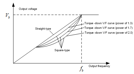
The VFD provides multiple V/F curve modes to meet different requirements. You can select V/F curves or set V/F curves as required.
Suggestions:
l For the load featuring constant moment, such as conveyor belt which runs in straight line, as the whole running process requires constant moment, it is recommended to adopt the straight line V/F curve.
l For the load featuring decreasing moment, such as fan and water pumps, as there is a power (square or cube) relation between its actual torque and speed, it is recommended to adopt the V/F curve corresponding to the power of 1.3, 1.7 or 2.0.
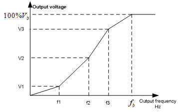
The VFD also provides multi-point V/F curves. You can change the V/F curves output by the VFD by setting the voltage and frequency of the three points in the middle. A whole curve consists of five points starting from (0Hz, 0V) and ending at (motor fundamental frequency, motor rated voltage). During setting, follow the rule: 0 ≤ f1 ≤ f2 ≤ f3 ≤ Motor fundamental frequency, and, 0 ≤ V1 ≤ V2 ≤ V3 ≤ Motor rated voltage
The VFD provides dedicated function codes for the space voltage control mode. You can improve the space voltage control performance by means of setting.
The VFD provides dedicated function codes for the space voltage control mode. You can improve the space voltage control performance by means of setting.
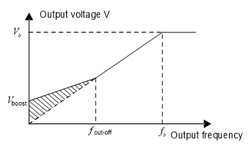
(1) Torque boost
The torque boost function can effectively compensate for the low-speed torque performance in space voltage control. Automatic torque boost has been set by default, which enables the VFD to adjust the torque boost value based on actual load conditions.
Note:
l Torque boost takes effect only at the torque boost cut-off frequency.
l If torque boost is too large, the motor may encounter low-frequency vibration or overcurrent. If such a situation occurs, reduce the torque boost value.
(2) Energy-saving run
During actual running, the VFD can search for the max. efficiency point to keep running in the most efficient state to save energy.
Note:
l This function is generally used in light load or no-load cases.
l This function is no applicable to the cases where sudden load changes often occur.
(3) V/F slip compensation gain
Space voltage vector control belongs to an open-loop mode. Sudden motor load changes cause motor speed fluctuation. In cases where strict speed requirements must be met, you can set the slip compensation gain to compensate for the speed change caused by load fluctuation through VFD internal output adjustment.
The setting range of slip compensation gain is 0–200%, in which 100% corresponds to the rated slip frequency.
Note: Rated slip frequency = (Rated synchronous rotation speed of motor – Rated rotation speed of motor) x (Number of motor pole pairs)/60
(4) Oscillation control
Motor oscillation often occurs in space voltage vector control in large-power driving applications. To solve this problem, the VFD provides two oscillation factor function codes. You can set the function codes based on the oscillation occurrence frequency.
Note: A greater value indicates better control effect. However, if the value is too large, the VFD output current may be too large.
(5) AM IF control
Generally, the IF control mode is valid for AMs. It can be used for SMs only when the frequency is extremely low. Therefore, the IF control mode described in this manual is only involved with AMs. IF control is implemented by performing closed-loop control on the total output current of the VFD. The output voltage adapts to the current reference, and open-loop control is separately performed over the frequency of the voltage and current.
Customized V/F curve (V/F separation) function:
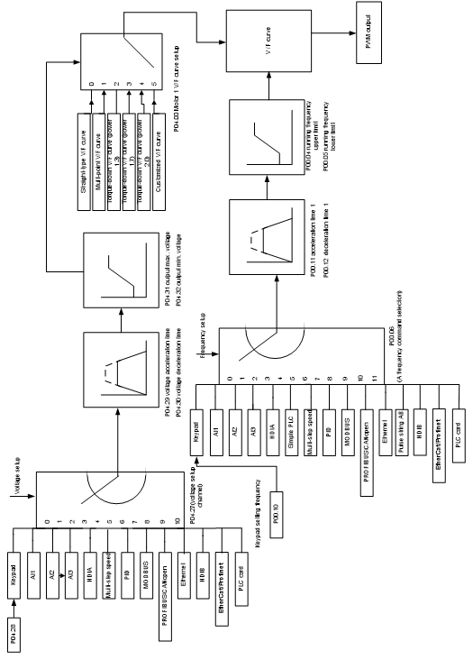
When selecting the customized V/F curve function, you can specify the setting channels and acceleration/deceleration time of voltage and frequency respectively, which form a real-time V/F curve in combination manner.
Note: This type of V/F curve separation can be applied in various variable-frequency power sources. However, exercise caution when setting parameters as improper settings may cause equipment damage.
Function code | Name | Description | Default |
Speed control mode | 0: Sensorless vector control (SVC) mode 0 1: Sensorless vector control (SVC) mode 1 2: Space voltage vector control mode 3: Closed-loop vector control mode Note: To select 0, 1, or 3 as the control mode, enable the VFD to perform motor parameter autotuning first. | 2 | |
Max. output frequency | P00.04–400.00Hz | 50.00Hz | |
Upper limit of running frequency | 50.00Hz | ||
Lower limit of running frequency | 0.00Hz–P00.04 | 0.00Hz | |
ACC time 1 | 0.0–3600.0s | Model depended | |
DEC time 1 | 0.0–3600.0s | Model depended | |
Type of motor 1 | 0: Asynchronous motor (AM) 1: Synchronous motor (SM) | 0 | |
Rated frequency of AM 1 | 0.01Hz–P00.03 (Max. output frequency) | 50.00Hz | |
Rated voltage of AM 1 | 0–1200V | Model depended | |
V/F curve setting of motor 1 | 0: Straight-line V/F curve 1: Multi-point V/F curve 2: Torque-down V/F curve (power of 1.3) 3: Torque-down V/F curve (power of 1.7) 4: Torque-down V/F curve (power of 2.0) 5: Customized V/F curve (V/F separation) | 0 | |
Torque boost of motor 1 | 0.0%: (automatic); 0.1%–10.0% | 0.0% | |
Torque boost cut-off of motor 1 | 0.0%–50.0% (of the rated frequency of motor 1) | 20.0% | |
V/F frequency point 1 of motor 1 | 0.00Hz–P04.05 | 0.00Hz | |
V/F voltage point 1 of motor 1 | 0.0%–110.0% | 0.0% | |
V/F frequency point 2 of motor 1 | 0.00Hz | ||
V/F voltage point 2 of motor 1 | 0.0%–110.0% | 0.0% | |
V/F frequency point 3 of motor 1 | 0.00Hz | ||
V/F voltage point 3 of motor 1 | 0.0%–110.0% | 0.0% | |
V/F slip compensation gain of motor 1 | 0.0–200.0% | 100.0% | |
Low-frequency oscillation control factor of motor 1 | 0–100 | 10 | |
High-frequency oscillation control factor of motor 1 | 0–100 | 10 | |
Oscillation control threshold of motor 1 | 0.00Hz–P00.03 (Max. output frequency) | 30.00Hz | |
V/F curve setting of motor 2 | 0: Straight-line V/F curve 1: Multi-point V/F curve 2: Torque-down V/F curve (power of 1.3) 3: Torque-down V/F curve (power of 1.7) 4: Torque-down V/F curve (power of 2.0) 5: Customized V/F curve (V/F separation) | 0 | |
Torque boost of motor 2 | 0.0%: (automatic); 0.1%–10.0% | 0.0% | |
Torque boost cut-off of motor 2 | 0.0%–50.0%(of the rated frequency of motor 1) | 20.0% | |
V/F frequency point 1 of motor 2 | 0.00Hz–P04.18 | 0.00Hz | |
V/F voltage point 1 of motor 2 | 0.0%–110.0% | 0.0% | |
V/F frequency point 2 of motor 2 | 0.00Hz | ||
V/F voltage point 2 of motor 2 | 0.0%–110.0% | 0.0% | |
V/F frequency point 3 of motor 2 | 0.00Hz | ||
V/F voltage point 3 of motor 2 | 0.0%–110.0% | 0.0% | |
V/F slip compensation gain of motor 2 | 0.0–200.0% | 100.0% | |
Low-frequency oscillation control factor of motor 2 | 0–100 | 10 | |
High-frequency oscillation control factor of motor 2 | 0–100 | 10 | |
Oscillation control threshold of motor 2 | 0.00Hz–P00.03 (Max. output frequency) | 30.00Hz | |
Energy-saving run | 0: Disable 1: Automatic energy-saving run | 0 | |
Voltage setting channel | 0: Keypad; Output voltage is determined by P04.28 1: AI1 2: AI2 3: AI3 4: HDIA 5: Multi-step running 6: PID 7: Modbus/Modbus TCP communication 8: Profibus/CANopen/DeviceNet communication 9: Ethernet communication 10: HDIB 11: EtherCat/Profinet/EtherNetIP communication 12: Programmable expansion card 13: Reserved | 0 | |
Voltage set through keypad | 0.0%–100.0%(of the motor rated voltage) | 100.0% | |
Voltage increase time | 0.0–3600.0s | 5.0s | |
Voltage decrease time | 0.0–3600.0s | 5.0s | |
Max. output voltage | P04.32–100.0% (of the motor rated voltage) | 100.0% | |
Min. output voltage | 0.0%–P04.31 (the motor rated voltage) | 0.0% | |
Weakening coefficient in constant power zone | 1.00–1.30 | 1.00 | |
Pull-in current 1 in SM V/F control | When the SM V/F control mode is enabled, the function code is used to set the reactive current of the motor when the output frequency is lower than the frequency specified by P04.36. Setting range:-100.0%–100.0% (of the motor rated current) | 20.0% | |
Pull-in current 2 in SM V/F control | When the SM V/F control mode is enabled, the function code is used to set the reactive current of the motor when the output frequency is higher than the frequency specified by P04.36. Setting range:-100.0%–100.0% (of the motor rated current) | 10.0% | |
Frequency threshold for pull-in current switching in SM V/F control | When the SM V/F control mode is enabled, the function code is used to set the frequency threshold for the switching between pull-in current 1 and pull-in current 2. Setting range: 0.00Hz–P00.03 (Max. output frequency) | 50.00Hz | |
Reactive current closed-loop proportional coefficient in SM V/F control | When the SM V/F control mode is enabled, the function code is used to set the proportional coefficient of reactive current closed-loop control. Setting range: 0–3000 | 50 | |
Reactive current closed-loop integral time in SM V/F control | When the SM V/F control mode is enabled, the function code is used to set the integral coefficient of reactive current closed-loop control. Setting range: 0–3000 | 30 | |
Reactive current closed-loop output limit in SM V/F control | When the SM V/F control mode is enabled, the function code is used to set the output limit of the reactive current closed-loop control. A greater value indicates a higher reactive closed-loop compensation voltage and higher output power of the motor. In general, you do not need to modify the function code. Setting range: 0–16000 | 8000 | |
Enabling IF mode of AM 1 | 0: Disable 1: Enable | 0 | |
Current setting in IF mode for AM 1 | When IF control is adopted for AM 1, the function code is used to set the output current. The value is a percentage in relative to the rated current of the motor. Setting range: 0.0–200.0% | 120.0% | |
Proportional coefficient in IF mode for AM 1 proportional coefficient | When IF control is adopted for AM 1, the function code is used to set the proportional coefficient of the output current closed-loop control. Setting range: 0–5000 | 650 | |
Integral coefficient in IF mode for AM 1 integral coefficient | When IF control is adopted for AM 1, the function code is used to set the integral coefficient of the output current closed-loop control. Setting range: 0–5000 | 350 | |
Frequency threshold for switching off IF mode for AM 1 | 0.00–P04.50 | 10.00Hz | |
Enabling IF mode for AM 2 | 0: Disable 1: Enable | 0 | |
Current setting in IF mode for AM 2 | When IF control is adopted for AM 2, the function code is used to set the output current. The value is a percentage in relative to the rated current of the motor. Setting range: 0.0–200.0% | 120.0% | |
Proportional coefficient in IF mode for AM 2 proportional coefficient | When IF control is adopted for AM 2, the function code is used to set the proportional coefficient of output current closed-loop control. Setting range: 0–5000 | 650 | |
Integral coefficient in IF mode for AM 2 integral coefficient | When IF control is adopted for AM 2, the function code is used to set the integral coefficient of output current closed-loop control. Setting range: 0–5000 | 350 | |
Frequency threshold for switching off IF mode for AM 2 | 0.00–P04.51 | 10.00Hz | |
P04.50 | End frequency point for switching off IF mode for AM 1 | P04.44–P00.03 | 25.00Hz |
P04.51 | End frequency point for switching off IF mode for AM 2 | P04.49 – P00.03 | 25.00Hz |