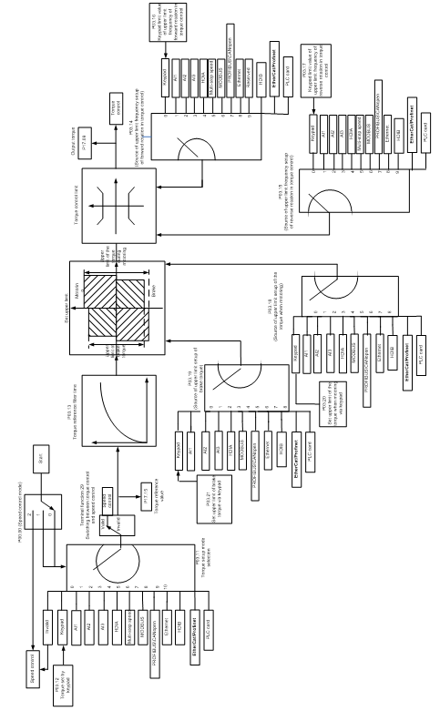
5.5.5 Torque control
The VFD supports torque control and speed control. Speed control aims to stabilize the speed to keep the set speed consistent with the actual running speed, meanwhile, the max. load-carrying capacity is restricted by the torque limit. Torque control aims to stabilize the torque to keep the set torque consistent with the actual output torque, meanwhile, the output frequency is restricted by the upper and lower limits.
Function code | Name | Description | Default |
Speed control mode | 0: Sensorless vector control (SVC) mode 0 1: Sensorless vector control (SVC) mode 1 2: Space voltage vector control mode 3: Closed-loop vector control mode Note: To select 0, 1, or 3 as the control mode, enable the VFD to perform motor parameter autotuning first. | 2 | |
Enabling torque control | 0: Disable 1: Enable | 0 | |
Torque setting method | 1: Keypad (P03.12) 2: AI1 (100% corresponding to three times the motor rated current) 3: AI2 (same as the above) 4: AI3 (same as the above) 5: Pulse frequency HDIA (same as the above) 6: Multi-step torque (same as the above) 7: Modbus/Modbus TCP communication (same as the above) 8: Profibus/CANopen/DeviceNet communication (same as the above) 9: Ethernet communication (same as the above) 10: Pulse frequency HDIB (same as the above) 11: EtherCat/Profinet/EtherNetIP communication 12: Programmable expansion card Note: For setting methods 2–12, 100% corresponds to three times the motor rated current. | 0 | |
Torque set through keypad | -300.0%–300.0% (of the motor rated current) | 50.0% | |
Torque reference filter time | 0.000–10.000s | 0.010s | |
Setting source of forward rotation upper-limit frequency in torque control | 0: Keypad (P03.16) 1: AI1 (100% corresponding to the max. frequency) 2: AI2 (same as the above) 3: AI3 (same as the above) 4: Pulse frequency HDIA (same as the above) 5: Multi-step setting (same as the above) 6: Modbus/Modbus TCP communication (same as the above) 7: Profibus/CANopen/DeviceNet communication (same as the above) 8: Ethernet communication (same as the above) 9: Pulse frequency HDIB (same as the above) 10: EtherCat/Profinet/EtherNetIP communication 11: Programmable expansion card 12: Reserved Note: For setting methods 1–11, 100% corresponds to the maximum frequency. | 0 | |
Setting source of reverse rotation upper-limit frequency in torque control | 0: Keypad (P03.17) 1: AI1 (100% corresponding to the max. frequency) 2: AI2 (same as the above) 3: AI3 (same as the above) 4: Pulse frequency HDIA (same as the above) 5: Multi-step setting (same as the above) 6: Modbus/Modbus TCP communication (same as the above) 7: Profibus/CANopen/DeviceNet communication (same as the above) 8: Ethernet communication (same as the above) 9: Pulse frequency HDIB (same as the above) 10: EtherCat/Profinet/EtherNetIP communication 11: Programmable expansion card 12: Reserved Note: For setting methods 1–11, 100% corresponds to the maximum frequency. | 0 | |
Forward rotation upper-limit frequency set through keypad in torque control | 0.00Hz–P00.03 (Max. output frequency) | 50.00 Hz | |
Reverse rotation upper-limit frequency set through keypad in torque control | 0.00Hz–P00.03 (Max. output frequency) | 50.00 Hz | |
Setting source of electromotive torque upper limit | 0: Keypad (P03.20) 1: AI1 (100% corresponding to three times the motor rated current) 2: AI2 (same as the above) 3: AI3 (same as the above) 4: Pulse frequency HDIA (same as the above) 5: Modbus/Modbus TCP communication (same as the above) 6: Profibus/CANopen/DeviceNet communication (same as the above) 7: Ethernet communication (same as the above) 8: Pulse frequency HDIB (same as the above) 9: EtherCat/Profinet/EtherNetIP communication 10: Programmable expansion card 11: Reserved Note: For setting methods 1–10, 100% corresponds to three times the motor rated current. | 0 | |
Setting source of braking torque upper limit | 0: Keypad (P03.21) 1: AI1 (100% corresponding to three times the motor rated current) 2: AI2 (same as the above) 3: AI3 (same as the above) 4: Pulse frequency HDIA (same as the above) 5: Modbus/Modbus TCP communication (same as the above) 6: Profibus/CANopen/DeviceNet communication (same as the above) 7: Ethernet communication (same as the above) 8: Pulse frequency HDIB (same as the above) 9: EtherCat/Profinet/EtherNetIP communication 10: Programmable expansion card 11: Reserved Note: For setting methods 1–10, 100% corresponds to three times the motor rated current. | 0 | |
Electromotive torque upper limit set through keypad | 0.0–300.0% (of the motor rated current) | 180.0% | |
Braking torque upper limit set through keypad | 0.0–300.0% (of the motor rated current) | 180.0% | |
Output torque | -250.0–250.0% | 0.0% | |
Torque reference value | -300.0–300.0% (of the motor rated current) | 0.0% |
5.5.6 Motor parameters
| ² Check the safety conditions surrounding the motor and load machineries before autotuning as physical injury may occur due to sudden start of motor during autotuning. ² Although the motor does not run during static autotuning, the motor is still supplied with power. Do not touch the motor during autotuning; otherwise, electric shock may occur. Do not touch the motor before autotuning is completed. |
| ² If the motor has been connected to a load, do not carry out rotary autotuning. Otherwise, the VFD may malfunction or may be damaged. If rotary autotuning is carried out on a motor which has been connected to a load, incorrect motor parameter settings and motor action exceptions may occur. Disconnect from the load to carry out autotuning if necessary. |


The VFD can drive both asynchronous motors and synchronous motors, and it supports two sets of motor parameters, which can be switched over by multifunction digital input terminals or communication modes.
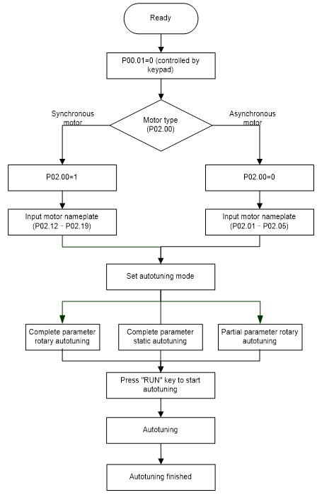
The control performance of the VFD is based on accurate motor models. Therefore, you need to carry out motor parameter autotuning before running a motor for the first time (taking motor 1 as an example).
Note:
l Motor parameters must be set correctly according to the motor nameplate.
l If rotary autotuning is selected during motor autotuning, disconnect the motor from the load to put the motor in static and no-load state. Otherwise, the motor parameter autotuning results may be incorrect. In addition, autotune P02.06–P02.10 for AMs and autotune P02.20–P02.23 for SMs.
l If static autotuning is selected for motor autotuning, there is no need to disconnect the motor from the load, but the control performance may be impacted as only a part of the motor parameters have been autotuned. In addition, autotune P02.06–P02.10 for AMs and autotune P02.20–P02.22 for SMs. P02.23 can be obtained through calculation.
l Motor autotuning can be carried out on the present motor only. If you need to perform autotuning on the other motor, switch the motor through selecting the switchover channel of motor 1 and motor 2 by setting the ones place of P08.31.
Related parameter list:
Function code | Name | Description | Default |
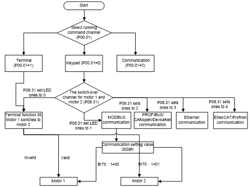
Channel of running commands | 0: Keypad 1: Terminal 2: Communication | 0 | |
Motor parameter autotuning | 0: No operation 1: Rotary autotuning 1. Comprehensive motor parameter autotuning. It is recommended to use rotating autotuning when high control accuracy is needed. 2: Static autotuning 1 (comprehensive autotuning); static autotuning 1 is used in cases where the motor cannot be disconnected from load. 3: Static autotuning 2 (partial autotuning); when the present motor is motor 1, only P02.06, P02.07 and P02.08 are autotuned; when the present motor is motor 2, only P12.06, P12.07 and P12.08 are autotuned. 4: Rotary autotuning 2. Similar to rotary autotuning 1, but it is valid only for AMs. 5: Static autotuning 3 (partial autotuning), valid only for AMs. | 0 | |
Type of motor 1 | 0: Asynchronous motor (AM) 1: Synchronous motor (SM) | 0 | |
Rated power of AM 1 | 0.1–3000.0kW | Model depended | |
Rated frequency of AM 1 | 0.01Hz–P00.03 (Max. output frequency) | 50.00Hz | |
Rated speed of AM 1 | 1–60000rpm | Model depended | |
Rated voltage of AM 1 | 0–1200V | Model depended | |
Rated current of AM 1 | 0.8–6000.0A | Model depended | |
Stator resistance of AM 1 | 0.001–65.535Ω | Model depended | |
Rotor resistance of AM 1 | 0.001–65.535Ω | Model depended | |
Leakage inductance of AM 1 | 0.1–6553.5mH | Model depended | |
Mutual inductance of AM 1 | 0.1–6553.5mH | Model depended | |
No-load current of AM 1 | 0.1–6553.5A | Model depended | |
Rated power of SM 1 | 0.1–3000.0kW | Model depended | |
Rated frequency of SM 1 | 0.01Hz–P00.03 (Max. output frequency) | 50.00Hz | |
Number of pole pairs of SM 1 | 1–50 | 2 | |
Rated voltage of SM 1 | 0–1200V | Model depended | |
Rated current of SM 1 | 0.8–6000.0A | Model depended | |
Stator resistance of SM 1 | 0.001–65.535Ω | Model depended | |
Direct-axis inductance of SM 1 | 0.01–655.35mH | Model depended | |
Quadrature-axis inductance of SM 1 | 0.01–655.35mH | Model depended | |
Counter-emf constant of SM 1 | 0–10000 | 300 | |
Function selection of multifunction digital input terminals (S1–S4, HDIA, HDIB) | 35: Switch from motor 1 to motor 2 | ||
Switching between motor 1 and motor 2 | 0x00–0x14 Ones place: Switchover channel 0: Terminal 1: Modbus/Modbus TCP communication 2: Profibus/CANopen/DeviceNet communication 3: Ethernet communication 4: EtherCat/Profinet/EtherNetIP communication Tens place: indicates whether to enable switchover during running 0: Disable 1: Enable | 00 | |
Type of motor 2 | 0: Asynchronous motor (AM) 1: Synchronous motor (SM) | 0 | |
Rated power of AM 2 | 0.1–3000.0kW | Model depended | |
Rated frequency of AM 2 | 0.01Hz–P00.03 (Max. output frequency) | 50.00Hz | |
Rated speed of AM 2 | 1–60000rpm | Model depended | |
Rated voltage of AM 2 | 0–1200V | Model depended | |
Rated current of AM 2 | 0.8–6000.0A | Model depended | |
Stator resistance of AM 2 | 0.001–65.535Ω | Model depended | |
Rotor resistance of AM 2 | 0.001–65.535Ω | Model depended | |
Leakage inductance of AM 2 | 0.1–6553.5mH | Model depended | |
Mutual inductance of AM 2 | 0.1–6553.5mH | Model depended | |
No-load current of AM 2 | 0.1–6553.5A | Model depended | |
Rated power of SM 2 | 0.1–3000.0kW | Model depended | |
Rated frequency of SM 2 | 0.01Hz–P00.03 (Max. output frequency) | 50.00Hz | |
Number of pole pairs of SM 2 | 1–50 | 2 | |
Rated voltage of SM 2 | 0–1200V | Model depended | |
Rated current of SM 2 | 0.8–6000.0A | Model depended | |
Stator resistance of SM 2 | 0.001–65.535Ω | Model depended | |
Direct-axis inductance of SM 2 | 0.01–655.35mH | Model depended | |
Quadrature-axis inductance of SM 2 | 0.01–655.35mH | Model depended | |
Counter-emf constant of SM 2 | 0–10000 | 300 |
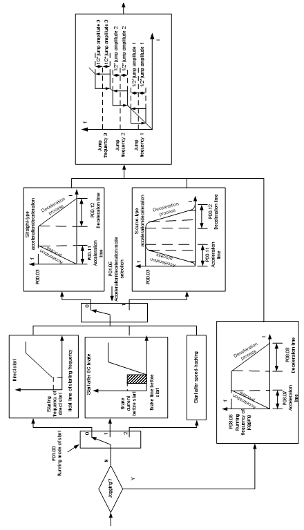
5.5.7 Start/stop control
The start/stop control of the VFD involves three states: start after a running command is given at power-on; start after power-off restart is effective; start after automatic fault reset. The three start/stop control states are described in the following.
There are three start modes for the VFD, which are start at starting frequency, start after DC braking, and start after speed tracking. You can select the proper start mode based on actual conditions.
For large-inertia load, especially in cases where reversal may occur, you can choose to start after DC braking or start after speed tracking.
Note: It is recommended to drive SMs in direct start mode.
(1) Logic diagram for start after a running command is given at power-on
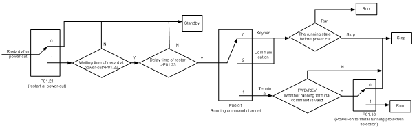
(2) Logic diagram for start after power-off restart is effective
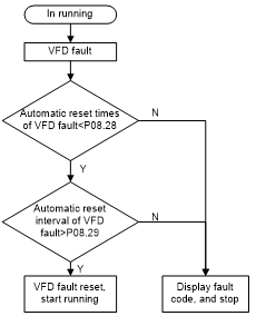
(3) Logic diagram for start after automatic fault reset
Related parameter list:
Function code | Name | Description | Default |
Channel of running commands | 0: Keypad 1: Terminal 2: Communication | 0 | |
ACC time 1 | 0.0–3600.0s | Model depended | |
DEC time 1 | 0.0–3600.0s | Model depended | |
Start mode | 0: Direct start 1: Start after DC braking 2: Speed tracking restart 1 3: Speed tracking restart 2 | 0 | |
Starting frequency of direct start | 0.00–50.00Hz | 0.50Hz | |
Starting frequency hold time | 0.0–50.0s | 0.0s | |
Braking current before start | 0.0–100.0% | 0.0% | |
DC braking time before start | 0.00–50.00s | 0.00s | |
ACC and DEC mode | 0: Linear 1: S curve Note: If mode 1 is selected, set P01.06, P01.07, P01.27, and P01.28 accordingly. | 0 | |
Stop mode | 0: Decelerate to stop 1: Coast to stop | 0 | |
Starting frequency of DC braking for stop | 0.00Hz–P00.03 (Max. output frequency) | 0.00Hz | |
Wait time before DC braking for stop | 0.00–50.00s | 0.00s | |
DC braking current for stop | 0.0–100.0% | 0.0% | |
DC braking time for stop | 0.00–50.00s | 0.00s | |
FWD/REV running deadzone time | 0.0–3600.0s | 0.0s | |
FWD/REV running switching mode | 0: Switch at zero frequency 1: Switch at the starting frequency 2: Switch after the speed reaches the stop speed with a delay | 0 | |
Stop speed | 0.00–100.00Hz | 0.50 Hz | |
Stop speed detection mode | 0: Detect by the set speed (unique in space voltage vector control mode) 1: Detect by the feedback speed | 1 | |
Terminal-based running command protection at power-on | 0: The terminal running command is invalid at power-on 1: The terminal running command is valid at power-on | 0 | |
Action selected when running frequency less than frequency lower limit (valid when frequency lower limit greater than 0) | 0: Run at the frequency lower limit 1: Stop 2: Sleep | 0 | |
Wake-up-from-sleep delay | 0.0–3600.0s (valid when P01.19=2) | 0.0s | |
Power-off restart selection | 0: Disable 1: Enable | 0 | |
Wait time for power-on restart | 0.0–3600.0s (valid when P01.21=1) | 1.0s | |
Start delay | 0.0–60.0s | 0.0s | |
Stop speed delay | 0.0–100.0s | 0.0s | |
Open-loop 0Hz output selection | 0: Output without voltage 1: Output with voltage 2: Output with the DC braking current for stop | 0 | |
DEC time for emergency stop | 0.0–60.0s | 2.0s | |
Time of starting segment of DEC S curve | 0.0–50.0s | 0.1s | |
Time of ending segment of DEC S curve | 0.0–50.0s | 0.1s | |
Short-circuit braking current | 0.0–150.0% (of the VFD rated current) | 0.0% | |
Hold time of short-circuit braking for start | 0.00–50.00s | 0.00s | |
Hold time of short-circuit braking for stop | 0.00–50.00s | 0.00s | |
Pre-exciting time of jog | 0–10.000s | 0.000s | |
Starting frequency of braking for jogging to stop | 0–P00.03 | 0.00Hz | |
Delay to enter sleep | 0–3600.0s | 0.0s | |
Digital input function selection | 1: Run forward 2: Run reversely 4: Jog forward 5: Jog reversely 6: Coast to stop 7: Reset faults 8: Pause running 21: ACC/DEC time selection 1 22: ACC/DEC time selection 2 30: Disable ACC/DEC | ||
ACC time 2 | 0.0–3600.0s | Model depended | |
DEC time 2 | 0.0–3600.0s | Model depended | |
ACC time 3 | 0.0–3600.0s | Model depended | |
DEC time 3 | 0.0–3600.0s | Model depended | |
ACC time 4 | 0.0–3600.0s | Model depended | |
DEC time 4 | 0.0–3600.0s | Model depended | |
Running frequency of jog | 0.00Hz–P00.03 (Max. output frequency) | 5.00Hz | |
ACC time for jog | 0.0–3600.0s | Model depended | |
DEC time for jog | 0.0–3600.0s | Model depended | |
Switching frequency of ACC/DEC time | 0.00–P00.03(Max. output frequency) 0.00Hz: No switchover If the running frequency is greater than P08.19, switch to ACC/DEC time 2. | 0 | |
Reference frequency of ACC/DEC time | 0: Max. output frequency 1: Set frequency 2: 100Hz Note: Valid only for straight-line ACC/DEC | 0 | |
Auto fault reset count | 0–10 | 0 | |
Auto fault reset interval | 0.1–3600.0s | 1.0s |
5.5.8 Frequency setting
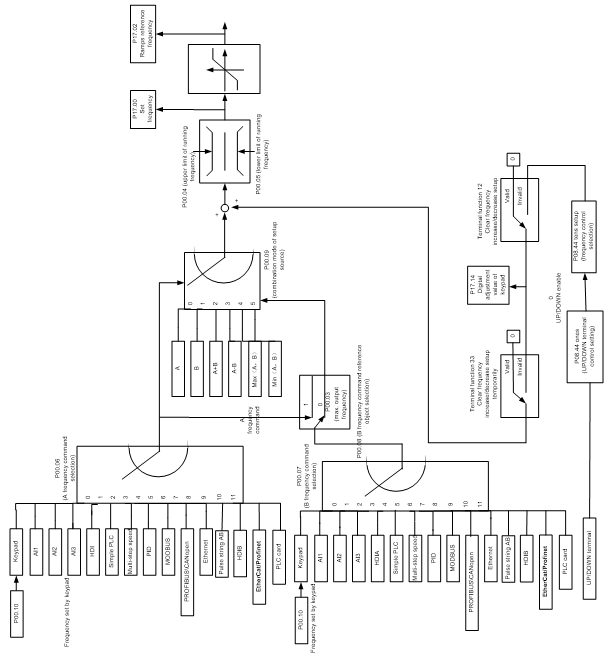
The VFD supports multiple frequency setting methods, which can be divided into two types: main reference channel and auxiliary reference channel.
There are two main reference channels, namely frequency reference channel A and frequency reference channel B. These two channels support simple arithmetical operation between each other, and they can be switched dynamically by setting multi-function terminals.
There is one input mode for auxiliary reference channel, namely terminal UP/DOWN switch input. By setting function codes, you can enable the corresponding reference mode and the impact made on the VFD frequency reference by this reference mode.
The actual reference of VFD is comprised of the main reference channel and auxiliary reference channel.
The VFD supports switchover between different reference channels, and the rules for channel switchover are shown in the following.
Present reference channel | Multifunction terminal function 13 Channel A switched to channel B | Multifunction terminal function 14 Combination setting switched to channel A | Multifunction terminal function 15 Combination setting switched to channel B |
A | B | / | / |
B | A | / | / |
A+B | / | A | B |
A-B | / | A | B |
Max(A,B) | / | A | B |
Min(A,B) | / | A | B |
Note: "/" indicates this multifunction terminal is invalid under present reference channel.
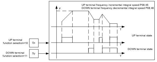
When setting the auxiliary frequency inside the VFD via multi-function terminal UP (10) and DOWN (11), you can increase/decrease the frequency quickly by setting P08.45 (UP terminal frequency incremental change rate) and P08.46 (DOWN terminal frequency decrement change rate).
Related parameter list:
Function code | Name | Description | Default |
Max. output frequency | P00.04–400.00Hz | 50.00Hz | |
Upper limit of running frequency | 50.00Hz | ||
Lower limit of running frequency | 0.00Hz–P00.04 | 0.00Hz | |
Setting channel of A frequency command | 0: Keypad 1: AI1 2: AI2 3: AI3 4: High-speed pulse HDIA 5: Simple PLC program 6: Multi-step speed running 7: PID control 8: Modbus/Modbus TCP communication 9: Profibus/CANopen/DeviceNet communication 10: Ethernet communication 11: High-speed pulse HDIB 12: Pulse train AB 13: EtherCat/Profinet/EtherNetIP communication 14: Programmable expansion card 15: Reserved | 0 | |
Setting channel of B frequency command | 15 | ||
Reference object of B frequency command | 0: Max. output frequency 1: A frequency command | 0 | |
Combination mode of setting source | 0: A 1: B 2: (A+B) 3: (A-B) 4: Max(A, B) 5: Min. (A, B) | 0 | |
Function selection of multifunction digital input terminals (S1–S4, HDIA, HDIB) | 10: Increase frequency setting (UP) 11: Decrease frequency setting (DOWN) 12: Clear the frequency increase/decrease setting 13: Switch between A setting and B setting 14: Switch between combination setting and A setting 15: Switch between combination setting and B setting | ||
Reserved | |||
Reserved | |||
UP/DOWN terminal control setting | 0x000–0x221 Ones place: Frequency setting selection 0: The setting made through UP/DOWN is valid. 1: The setting made through UP/DOWN is invalid. Ones place: Frequency control selection 0: Valid only when P00.06=0 or P00.07=0 1: Valid for all frequency setting methods 2: Invalid for multi-step speed running when multi-step speed running has the priority Hundreds place: Action selection for stop 0: Setting is valid. 1: Valid during running, cleared after stop 2: Valid during running, cleared after a stop command is received | 0x000 | |
Frequency increment change rate of the UP terminal | 0.01–50.00 Hz/s | 0.50 Hz/s | |
Frequency decrement change rate of the DOWN terminal | 0.01–50.00 Hz/s | 0.50 Hz/s | |
Set frequency | 0.00Hz–P00.03 (Max. output frequency) | 0.00Hz | |
Ramp reference frequency | 0.00Hz–P00.03 (Max. output frequency) | 0.00Hz | |
Digital adjustment value | 0.00Hz–P00.03 | 0.00Hz |
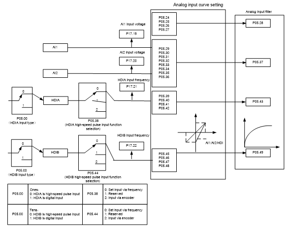
5.5.9 Analog input
The VFD provides two analog input terminals, which are AI1 supporting 0–10V/0–20mA, (whether the input is voltage or current can be set by P05.50), and AI2 supporting -10–10V, and two high-speed pulse input terminals. Each input can be filtered separately, and the corresponding reference curve can be set by adjusting the reference corresponds to the max. value and min. value.
Related parameter list:
Function code | Name | Description | Default |
HDI input type | 0x00–0x11 Ones place: HDIA input type 0: HDIA is high-speed pulse input 1: HDIA is digital input Tens place: HDIB input type 0: HDIB is high-speed pulse input 1: HDIB is digital input | 0x00 | |
AI1 lower limit | 0.00V–P05.26 | 0.00V | |
Corresponding setting of AI1 lower limit | -300.0%–300.0% | 0.0% | |
AI1 upper limit | P05.24–10.00V | 10.00V | |
Corresponding setting of AI1 upper limit | -300.0%–300.0% | 100.0% | |
AI1 input filter time | 0.000s–10.000s | 0.100s | |
AI2 lower limit | -10.00V–P05.31 | -10.00V | |
Corresponding setting of AI2 lower limit | -300.0%–300.0% | -100.0% | |
AI2 middle value 1 | 0.00V | ||
Corresponding setting of AI2 middle value 1 | -300.0%–300.0% | 0.0% | |
AI2 middle value 2 | 0.00V | ||
Corresponding setting of AI2 middle value 2 | -300.0%–300.0% | 0.0% | |
AI2 upper limit | P05.33–10.00V | 10.00V | |
Corresponding setting of AI2 upper limit | -300.0%–300.0% | 100.0% | |
AI2 input filter time | 0.000s–10.000s | 0.100s | |
HDIA high-speed pulse input function selection | 0: Input set through frequency 1: Reserved 2: Input set through encoder, used together with HDIB | 0 | |
HDIA lower limit frequency | 0.000 kHz – P05.41 | 0.000kHz | |
Corresponding setting of HDIA lower limit frequency | -300.0%–300.0% | 0.0% | |
HDIA upper limit frequency | P05.39 –50.000kHz | 50.000kHz | |
Corresponding setting of HDIA upper limit frequency | -300.0%–300.0% | 100.0% | |
HDIA frequency input filter time | 0.000s–10.000s | 0.030s | |
HDIB high-speed pulse input function selection | 0: Input set through frequency 1: Reserved 2: Input set through encoder, used together with HDIA | 0 | |
HDIB lower limit frequency | 0.000 kHz – P05.47 | 0.000kHz | |
Corresponding setting of HDIB lower limit frequency | -300.0%–300.0% | 0.0% | |
HDIB upper limit frequency | P05.45 –50.000kHz | 50.000kHz | |
Corresponding setting of HDIB upper limit frequency | -300.0%–300.0% | 100.0% | |
HDIB frequency input filter time | 0.000s–10.000s | 0.030s | |
AI1 input signal type | 0–1 0: Voltage 1: Current | 0 |
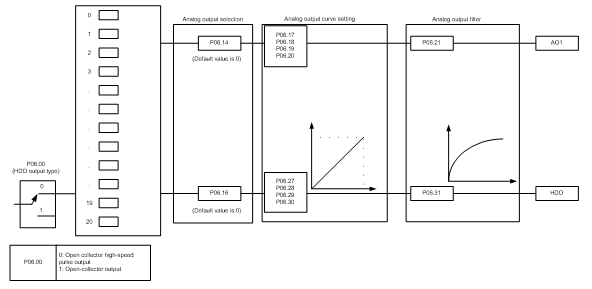
5.5.10 Analog output
The VFD provides one analog output terminal (supporting 0–10V/0–20mA) and one high-speed pulse output terminal. Analog output signals can be filtered separately, and the proportional relation can be adjusted by setting the max. value, min. value, and the percentage of their corresponding output. Analog output signals can output the motor speed, output frequency, output current, motor torque and motor power at a certain proportion.
Terminal output is described as follows:
Setting | Function | Description |
0 | Running frequency | 0–Max. output frequency |
1 | Set frequency | 0–Max. output frequency |
2 | Ramp reference frequency | 0–Max. output frequency |
3 | Running speed | 0–Synchronous speed corresponding to max. output frequency |
4 | Output current (relative to VFD) | 0–Twice the VFD rated current |
5 | Output current (relative to motor) | 0–Twice the motor rated current |
6 | Output voltage | 0–1.5 times the VFD rated voltage |
7 | Output power | 0–Twice the rated power |
8 | Set torque value (bipolar) | 0–Twice the VFD rated current. A negative value corresponds to 0.0% by default. |
9 | Output torque (absolute value) | 0 – +/-(Twice the motor rated torque) |
10 | AI1 input | 0–10V/0–20mA |
11 | AI2 input | 0V–10V. A negative value corresponds to 0.0% by default. |
12 | AI3 input | 0–10V/0–20mA |
13 | High-speed pulse HDIA input | 0.00–50.00kHz |
14 | Value 1 set through Modbus/Modbus TCP communication | 0–1000 |
15 | Value 2 set through Modbus/Modbus TCP communication | 0–1000 |
16 | Value 1 set through PROFIBUS/CANopen/DeviceNet communication | 0–1000 |
17 | Value 2 set through PROFIBUS/CANopen/DeviceNet communication | 0–1000 |
18 | Value 1 set through Ethernet communication | 0–1000 |
19 | Value 2 set through Ethernet communication | 0–1000 |
20 | High-speed pulse HDIA input | 0.00–50.00kHz |
21 | Value 1 set through EtherCAT/Profinet/EtherNetIP communication | 0–1000. A negative value corresponds to 0.0% by default. |
22 | Torque current (bipolar) | 0–Three times the motor rated current. A negative value corresponds to 0.0% by default. |
23 | Exciting current | 0–Three times the motor rated current. A negative value corresponds to 0.0% by default. |
24 | Set frequency (bipolar) | 0–Max. output frequency. A negative value corresponds to 0.0% by default. |
25 | Ramp reference frequency (bipolar) | 0–Max. output frequency. A negative value corresponds to 0.0% by default. |
26 | Rotational speed (bipolar) | 0–Synchronous speed corresponding to max. output frequency A negative value corresponds to 0.0% by default. |
27 | Value 2 set through EtherCat/Profinet/EtherNetIP communication | 0–1000 |
28 | C_AO1 from PLC | 0–1000 |
29 | C_AO2 from PLC | 0–1000 |
30 | Rotational speed | 0–Twice the motor rated synchronous speed |
31 | Output torque (bipolar) | 0–Twice motor rated torque. A negative value corresponds to 0.0% by default. |
31–47 | Reserved |
Related parameter list: