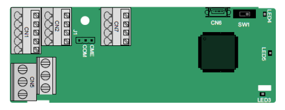
The terminals are arranged as follows:
SW1 is the start/stop switch of the programmable extension card. CN6 is the program download port, and you can connect to a computer by using a standard USB cable. COM and CME are shorted through J1 before delivery.
| PY1 | PY2 | CME | COM |
COM | PS1 | PS2 | PS3 | PRO1A | PRO1B | PRO1C | |||||
PW | +24V | PS4 | PS5 | PS6 | PRO2A | PRO2C | |||||
Indicator definition
Indicator No. | Definition | Function |
LED3 | State indicator | This indicator is on when the extension card is establishing a connection with the control board; it blinks periodically after the extension card is properly connected to the control board (the period is 1s, on for 0.5s, and off for the other 0.5s); and it is off when the extension card is disconnected from the control board. |
LED4 | PLC running state indicator | This indicator is on when the DIP switch is turned to RUN (run the PLC); and it is off when the switch is turned to STOP (stop the PLC). |
LED5 | Power indicator | This indicator is on after the control board feeds power to the communication card. |
The EC-PC501-00 programmable extension card can replace some micro PLC applications. It adopts the global mainstream development environment, supporting six types of programming languages, namely the instruction language (IL), structural text (ST), function block diagram (FBD), ladder diagram (LD), continuous function chart (CFC), and sequential function chart (SFC). It provides a user program storage space of 128 kB and data storage space of 64 kB, which facilitates customers' secondary development and meets the customization requirements.
The EC-PC501-00 programmable extension card provides 6 digital inputs, 2 digital outputs, and 2 relay outputs. It is user-friendly, providing relay outputs through European-type screw terminals and other inputs and outputs through spring terminals.
EC-PC501-00 terminal function description
Category | Label | Name | Function description |
Power | PW | External power | The working power of digital input is provided by an external power supply. Voltage range: 12–30 V The terminals PW and +24V are shorted before delivery. |
Digital input/output | PS1—COM | Digital input 1 | 1. Internal impedance: 3.3 kΩ 2. Allowable voltage input: 12–30 V 3. Bidirectional terminal 4. Max. input frequency: 1 kHz |
PS2—COM | Digital input 2 | ||
PS3—COM | Digital input 3 | ||
PS4—COM | Digital input 4 | ||
PS5—COM | Digital input 5 | ||
PS6—COM | Digital input 6 | ||
PY1—CME | Digital output 1 | 1. Switch capacity: 50 mA/30 V 2. Output frequency range: 0–1 kHz 3. The terminals CME and COM are shorted through J1 before delivery. | |
PY2—CME | Digital output 2 | ||
Relay output | PRO1A | NO contact of relay 1 | 1. Contact capacity: 3A/AC 250 V, 1 A/DC 30 V 2. Do not use them as high-frequency digital outputs. |
PRO1B | NC contact of relay 1 | ||
PRO1C | Common contact of relay 1 | ||
PRO2A | NO contact of relay 2 | ||
PRO2C | Common contact of relay 2 |
For details about the operation of programmable extension cards, see the Goodrive350 Series VFD Communication Extension Card Operation Manual.