A.6.1 Bluetooth communication card
EC-TX501 and WIFI communication card––EC- TX502
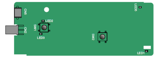
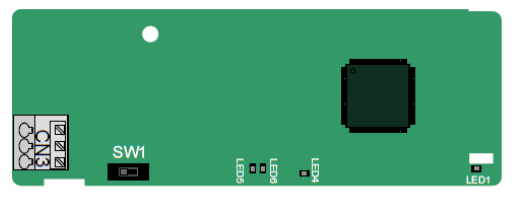
Definitions of indicators and function buttons:
Indicator No. | Definition | Function |
LED1/LED3 | Bluetooth/WIFI state indicator | LED is on when the extension card is establishing a connection with the control board; LED blinks periodically after the extension card is properly connected to the control board (the period is 1s, on for 0.5s, and off for the other 0.5s); and LED is off when the extension card is disconnected from the control board. |
LED2 | Bluetooth communication state indicator | This indicator is on when Bluetooth communication is online and data exchange can be performed. It is off when Bluetooth communication is not in the online state. |
LED5 | Power indicator | This indicator is on after the control board feeds power to the Bluetooth card. |
SW1 | WIFI factory reset button | It is restored to default values and returned to the local monitoring mode. |
SW2 | WIFI hardware reset button | It is used to reboot the extension card. |
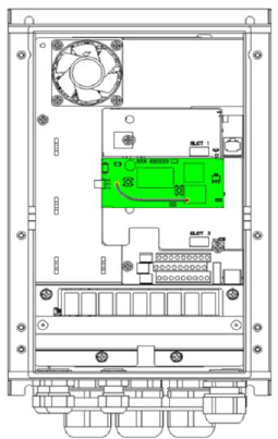
The wireless communication card is especially useful for scenarios where you cannot directly use the keypad to operate the VFD due to the restriction of the installation space. With a mobile phone APP, you can operate the VFD in a maximum distance of 30 m. You can choose a PCB antenna or an external sucker antenna. If the VFD is located in an open space and is a molded case machine, you can use a built-in PCB antenna; and if it is a sheetmetal machine and located in a metal cabinet, you need to use an external sucker antenna.
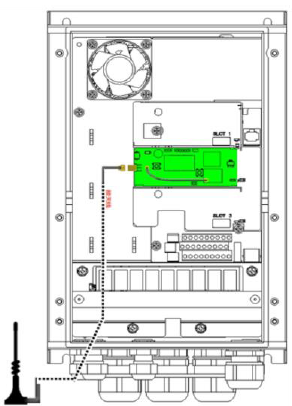
When installing a sucker antenna, install a wireless communication card on the VFD first, and then lead the SMA connector of the sucker antenna into the VFD and screw it to CN2, as shown in the following figure. Place the antenna base on the chassis and expose the upper part. Try to keep it unblocked.
|  |
|
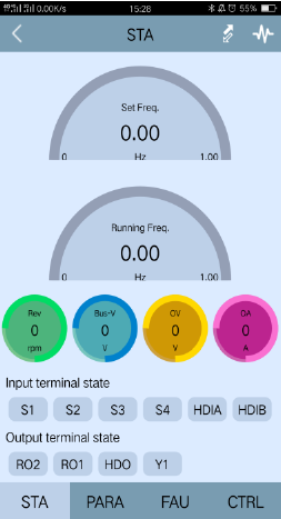
The wireless communication card must be used with the INVT VFD APP. Scan the QR code of the VFD nameplate to download it. For details, refer to the wireless communication card manual provided with the extension card. The main interface is shown as follows.
|  |
|

A.6.2 PROFIBUS-DP communication card
EC-TX503
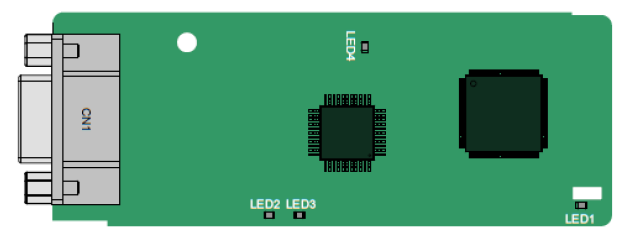
CN1 is a 9-pin D-type connector, as shown in the following figure.
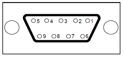
Connector pin | Description | |
1 | - | Unused |
2 | - | Unused |
3 | B-Line | Data+ (twisted pair 1) |
4 | RTS | Request sending |
5 | GND_BUS | Isolation ground |
6 | +5V BUS | Isolated power supply of 5 V DC |
7 | - | Unused |
8 | A-Line | Data- (twisted pair 2) |
9 | - | Unused |
Housing | SHLD | PROFIBUS cable shielding line |
+5V and GND_BUS are bus terminators. Some devices, such as the optical transceiver (RS485), may need to obtain power through these pins.
On some devices, the transmission and receiving directions are determined by RTS. In normal applications, only A-Line, B-Line, and the shield layer need to be used.
Indicator definition
Indicator No. | Definition | Function |
LED1 | State indicator | This indicator is on when the extension card is establishing a connection with the control board; it blinks periodically after the extension card is properly connected to the control board (the period is 1s, on for 0.5s, and off for the other 0.5s); and it is off when the extension card is disconnected from the control board. |
LED2 | Online indicator | This indicator is on when the communication card is online and data exchange can be performed. It is off when the communication card is not in the online state. |
LED3 | Offline/Fault indicator | This indicator is on when the communication card is offline and data exchange cannot be performed. It blinks when the communication card is not in the offline state. It blinks at the frequency of 1 Hz when a configuration error occurs: The length of the user parameter data set during the initialization of the communication card is different from that during the network configuration. It blinks at the frequency of 2 Hz when user parameter data is incorrect: The length or content of the user parameter data set during the initialization of the communication card is different from that during the network configuration. It blinks at the frequency of 4 Hz when an error occurs in the ASIC initialization of PROFIBUS communication. It is off when the diagnosis function is disabled. |
LED4 | Power indicator | This indicator is on after the control board feeds power to the communication card. |
For details about the operation, see the Goodrive350 Series VFD Communication Extension Card Operation Manual.
A.6.3 Ethernet communication card
EC-TX504
The EC-TX504 communication card adopts standard RJ45 terminals.
Indicator definition
Indicator No. | Definition | Function |
LED1 | State indicator | This indicator is on when the extension card is establishing a connection with the control board; it blinks periodically after the extension card is properly connected to the control board (the period is 1s, on for 0.5s, and off for the other 0.5s); and it is off when the extension card is disconnected from the control board. |
LED4 | Power indicator | This indicator is on after the control board feeds power to the communication card. |
A.6.4 CANopen communication card
EC-TX505 and CAN master/slave control communication card EC- TX511
The EC-TX505 communication card is user-friendly, adopting spring terminals.
3-pin spring terminal | Pin | Function | Description |
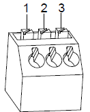 | 1 | CANH | CANopen bus high level signal |
2 | CANG | CANopen bus shielding | |
3 | CANL | CANopen bus low level signal |
Terminal resistor switch function description
Terminal resistor switch | Position | Function | Description |
| Left | OFF | CAN_H and CAN_L are not connected to a terminal resistor. |
Right | ON | CAN_H and CAN_L are connected to a terminal resistor of 120 Ω. |

Indicator definition
Indicator No. | Definition | Function |
LED1 | State indicator | This indicator is on when the extension card is establishing a connection with the control board; it blinks periodically after the extension card is properly connected to the control board (the period is 1s, on for 0.5s, and off for the other 0.5s); and it is off when the extension card is disconnected from the control board. |
LED4 | Power indicator | This indicator is on after the control board feeds power to the communication card. |
LED5 | Running indicator | This indicator is on when the communication card is in the working state. It is off when a fault occurs. Check whether the reset pin of the communication card and the power supply are properly connected. It blinks when the communication card is in the pre-operation state. It blinks once when the communication card is in the stopped state. |
LED6 | Error indicator | This indicator is on when the CAN controller bus is off or a fault occurs on the VFD. It is off when the communication card is in the working state. It blinks when the address setting is incorrect. It blinks once when a received frame is missed or an error occurs during frame receiving. |
For details about the operation, see the Goodrive350 Series VFD Communication Extension Card Operation Manual.
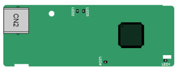
A.6.5 PROFINET communication card
EC- TX509
The terminal CN2 adopts a standard RJ45 interface, where CN2 is the dual RJ45 interface, and these two RJ45 interfaces are not distinguished from each other and can be interchangeably inserted. They are arranged as follows:
Pin | Name | Description |
1 | n/c | Not connected |
2 | n/c | Not connected |
3 | RX- | Receive Data- |
4 | n/c | Not connected |
5 | n/c | Not connected |
6 | RX+ | Receive Data+ |
7 | TX- | Transmit Data- |
8 | TX+ | Transmit Data+ |
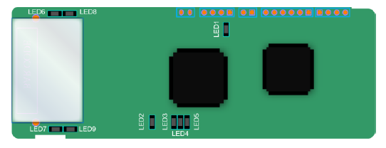
Definition of the state indicator
The PROFINET communication card has 9 indicators, of which LED1 is the power indicator, LED2–5 are the communication state indicator of the communication card, and LED6–9 are the state indicators of the network port.
LED | Color | State | Description |
LED1 | Green | / | 3.3V power indicator |
LED2 (Bus state indicator) | Red | On | No network connection |
Blinking | The connection to the network cable between the PROFINET controller is OK, but the communication is not established. | ||
Off | Communication with the PROFINET controller has been established | ||
LED3 (System fault indicator) | Green | On | PROFINET diagnosis exists |
Off | No PROFINET diagnosis | ||
LED4 (Slave ready indicator) | Green | On | TPS-1 protocol stack has started |
Blinking | TPS-1 waits for MCU initialization | ||
Off | TPS-1 protocol stack does not start | ||
LED5 (Maintenance state indicator) | Green | / | Manufacturer-specific–depending on the characteristics of the device |
LED6/7 (Network port state indicator) | Green | On | PROFINET communication card and PC/PLC have been connected via a network cable |
Off | PROFINET communication card and PC/PLC have not been connected yet | ||
LED8/9 (Network port communication indicator) | Green | Blinking | PROFINET communication card and PC/PLC are communicating |
Off | PROFINET communication card and PC/PLC are not yet communicating |
Electrical connection:
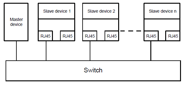
The PROFINET communication card adopts a standard RJ45 interface, which can be used in a linear network topology and a star network topology. The linear network topology electrical connection diagram is shown below.
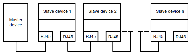
Linear network topology electrical connection diagram
Note: For the star network topology, users need to prepare PROFINET switches.
The star network topology electrical connection diagram is shown below: